A level reading is only as trustworthy as its reference point, process conditions, and signal path. By the end, you will be able to plan a safe calibration, select the right reference and method, calculate expected outputs, test different sensor technologies, and document the result.
Key takeaways
- Define zero and span from the control system’s engineering points.
- Isolate pressure, temperature, power, and process hazards before calibration.
- Test sensor output at 0%, 25%, 50%, 75%, and 100%.
- Record as-found, adjusted, and as-left readings with traceable references.
Define the measurement and make the installation safe
A level sensor calibration procedure begins by naming the measurand and datum: liquid elevation above the tank bottom, volume, mass, or distance below a radar or ultrasonic reference plane. Define the control system’s engineering zero and 100% points; an empty vessel is not automatically zero, and the geometric top is not automatically full scale.
1. Record the instrument tag, measurement technology, range, units, wiring, configuration, and as-found output before changing anything.
2. Apply lockout/tagout and electrical isolation. Bypass the control loop and secure tank-access controls so calibration cannot start equipment or expose personnel.
3. Check process pressure, temperature, agitation, chemical compatibility, and exposure to toxic, flammable, or corrosive liquid.
4. Obtain a hazardous-area permit where required. In an ATEX installation, open an enclosure or connect test equipment only after the equipment certificate and site procedure confirm permission; use intrinsically safe equipment when specified.
5. Let the process and electronics stabilise. Keep damping, range values, wiring, and tank conditions unchanged during the test.
6. For a differential-pressure transmitter, establish the actual port pressures at empty and full conditions, including zero suppression, zero elevation, or a wet-reference-leg head.
7. Record reference equipment identification, calibration due date, test points, process temperature and density where relevant, adjustments, tolerance, operator, and date.
This foundation separates calibration error from installation or process error.
Choose a reference and perform the zero-to-span test
Create a valid level reference by tying a known liquid height or input to the control system’s defined zero and span. For an accessible tank, use a dip tape or calibrated rule; use a sight glass only when clean and unobstructed.
Other choices include calibrated tank volume with controlled filling or a certified portable reference instrument. Select equipment whose resolution and uncertainty support the required tolerance. Record its identification, calibration due date, resolution, and uncertainty. Read the reference and sensor simultaneously after the liquid settles. Exclude readings during sloshing, foaming, filling, discharge, or severe temperature stratification.
| Method | Reference | Use |
|---|---|---|
| Wet calibration | At least two known liquid levels tied to zero and span | Create real process levels |
| Dry bench calibration | Simulated input, pressure source, distance target, resistance, or approved fixture | Use when liquid levels are unsafe or impractical |
| Two-point comparison | Zero and span | Check endpoint error |
| Multipoint comparison | Zero, 25%, 50%, 75%, and span | Reveal nonlinearity, wrong tank geometry, or a bad reference |
Use these level sensor calibration steps:
- Record as-found readings at each point.
- Adjust zero first, then span.
- Repeat every point because changing span can move zero.
- Reject forced offsets when a mechanical fault, blocked impulse line, bad sight glass, or false echo causes the error.
These level sensor calibration methods verify an instrument; they do not repair the installation.
Apply the right procedure to each sensing technology
Use the technology-specific checks in the level sensor calibration procedure before changing transmitter settings. Correct an installation fault first; an offset adjustment will not fix a sticking float, false echo, or wrong process model.
| Technology | Checks before adjustment | Calibration basis |
|---|---|---|
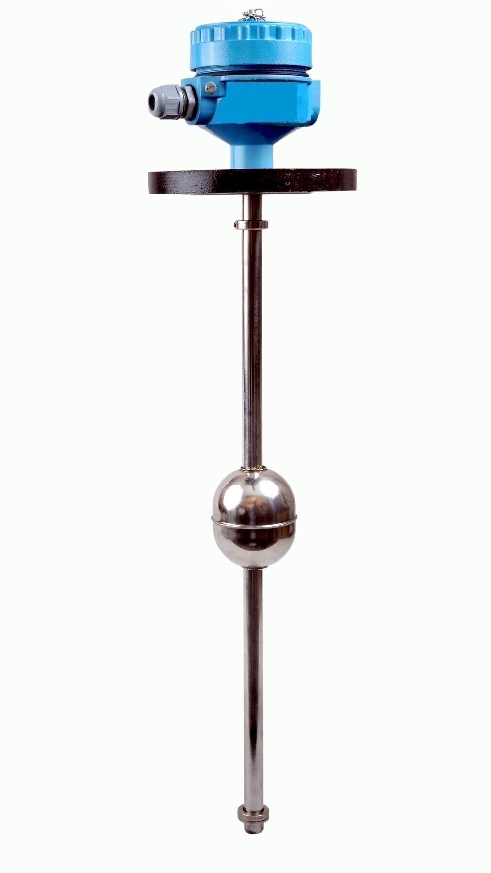
| Float | Confirm float freedom, guide movement, cable or linkage condition, and pulley alignment. Establish the actual mechanical zero and span. | Adjust the transmitter only after the mechanism reaches both true endpoints. |
| Hydrostatic | Apply ΔP = ρgh using actual process density, gravitational head, and transmitter elevation. On a closed vessel, check zero suppression, zero elevation, and any wet reference-leg head. | Calibrate pressure at the transmitter ports for stated empty and full conditions—not automatically 0 and nominal maximum. |
| Ultrasonic | Verify the transducer reference plane, tank height, dead zone, gas temperature, vapour, foam, turbulence, and sound-path obstructions. | Compensate environmental effects or change technology when the sound path is unreliable. |
| Radar | Check antenna reference height and echo profile for agitators, inlets, condensation, multiple reflections, and false echoes. | Correct the reference plane, tank mapping, or obstruction before changing range values. |
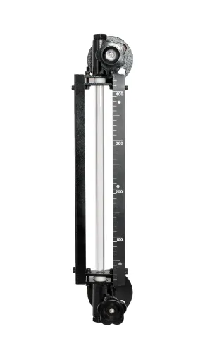
| Magnetic gauge | Clean the chamber, free the float, confirm isolation, and align the float with the indicator. | Compare the local reading with a sight glass or dip measurement. |
| Fuel tank or capacitance | Check installed tank geometry, probe length, fuel condition, wiring, specified dielectric condition, and probe coating. | Use the manufacturer’s adjustment limits and installed configuration. |
Filpro Sensors Pvt Ltd can help distinguish a calibration fault from an installation or configuration error when these checks do not agree. Reverify at empty, full, and an intermediate level before returning the device to service.
Related products
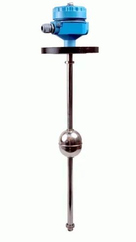
 | Level Sensor Atex approved Float Level Transmitter : Over All Length: 300mm to 5000mm Input: 16V DC to 30V DC Output: 4-20mA / 0-10V DC Resolution: 5mm / 10mm... View product → |
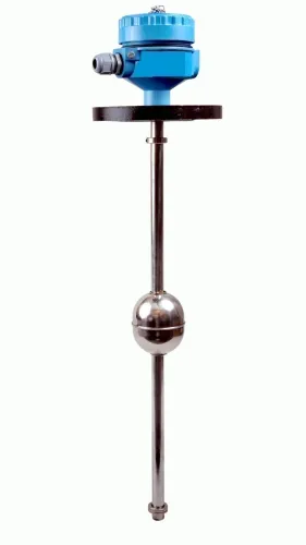
 | Level Transmitter Float Level Transmitters Are Ideal For Continuous Level Monitoring In Water, Diesel, Chemical And Oils For Accurate Level Measurement. View product → |
Calculate and test 4–20 mA, voltage, and digital outputs
Prove the output by applying known reference levels, calculating the expected signal, and comparing that value with both the transmitter indication and the receiving system. These level sensor calibration methods test separate failure points: a correct internal level value does not prove that loop-output trim is correct.
1. For a linear 4–20 mA transmitter, calculate expected current with I = 4 + 16 × (L − L0) ÷ (L100 − L0), where L is measured level and L0 and L100 are configured zero and full-scale levels.
Test 0%, 25%, 50%, 75%, and 100%: the expected outputs are 4, 8, 12, 16, and 20 mA.
2. Convert measured current back to level with L = L0 + (I − 4) × (L100 − L0) ÷ 16. Compare that result with the reference level, local indication, and PLC or DCS value; check alarm thresholds and high-high or low-low shutdown actions.
3. Test sensor indication and analog output separately. Before connecting a calibrator, confirm output loading, common reference, polarity, and permitted signal range. For 0–10 V, test 0, 2.5, 5, 7.5, and 10 V; for 0–5 V, test 0, 1.25, 2.5, 3.75, and 5 V.
4. For RS-485 or RS-232, verify the digital level variable, units, address, baud rate, parity, stop bits, scaling, and update rate. Do not treat a digital connection as an analog signal.
5. Record whether each adjustment changed sensor trim, analog-output trim, or digital scaling.
Verify the complete loop and close the calibration record
Calibration is complete and defensible only after you repeat the zero, 25%, 50%, 75%, and 100% checks where the process allows. These final level sensor calibration steps must prove the complete signal path, not only the transmitter.
| Check | Compare | What failure means |
|---|---|---|
| Sensor | Actual reference level and sensor indication | Sensor trim or reference datum error |
| Local display | Transmitter value and displayed engineering units | Display configuration or unit error |
| Analog output | Measured current or voltage and configured range | Output trim, polarity, or range error |
| Digital value | Communicated variable and engineering units | Protocol mapping or scaling error |
| PLC or DCS | Displayed value and transmitter value | Incorrect conversion, range, or units |
| Alarms | Alarm thresholds against tested values | Wrong setpoint or alarm logic |
| Shutdowns | High-high and low-low actions | Bypass, interlock, or trip logic remains incorrect |
Restore the loop from bypass, remove temporary test wiring, close every enclosure, and confirm that alarms and interlocks have returned to their approved operating state. Investigate errors that change with liquid density, temperature, vessel pressure, fill direction, or agitation; do not apply another zero or span adjustment.
Those patterns indicate an incorrect process model, impulse-line condition, reference-leg problem, echo-quality fault, or unsuitable reference datum.
Close the record with the instrument tag and measurement principle, datum, configured range, as-found and as-left readings, every test point, reference equipment identification and due date, relevant temperature and density, acceptance tolerance or uncertainty, adjustments made, trim type, and the person and date. Final 4–20 mA values alone cannot support an audit or future troubleshooting.
Frequently asked questions
What should you define before calibrating a level sensor?
Define the measurand and datum, then identify the engineering zero and 100% points. These points may differ from an empty vessel and its geometric top.
How do you perform a zero-to-span level sensor test?
Choose a traceable reference, establish the zero point, apply the span point, and test intermediate levels. Compare the sensor reading with the reference at each test point.
Do different level sensing technologies require different calibration methods?
Yes. Radar and ultrasonic sensors require correct reference-plane and distance settings, while hydrostatic, capacitive, float, and displacer devices require technology-specific checks.
How do you verify a 4–20 mA level signal?
Test the loop at defined level points and confirm 4 mA at 0%, 12 mA at 50%, and 20 mA at 100%, unless the instrument uses a documented alternative range.
What belongs in a level sensor calibration record?
Record the tag number, instrument range, reference used, environmental and process conditions, as-found readings, adjustments, as-left readings, output checks, technician, date, and acceptance criteria.
Related products
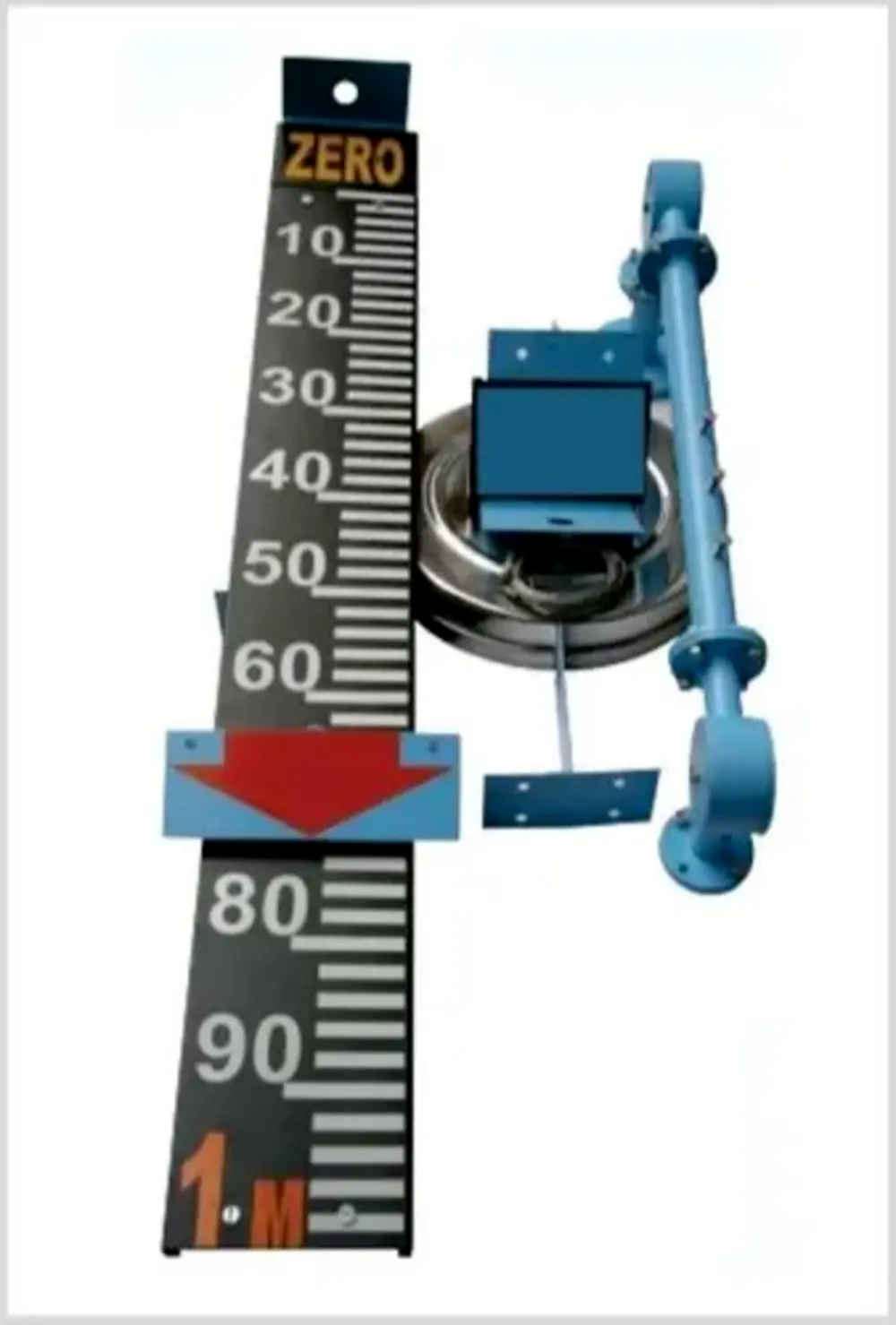 | Level Indicator The Float & Board Level Indicators consists of a float connected to a pointerthrough a rope via a set of pulleys. View product → |
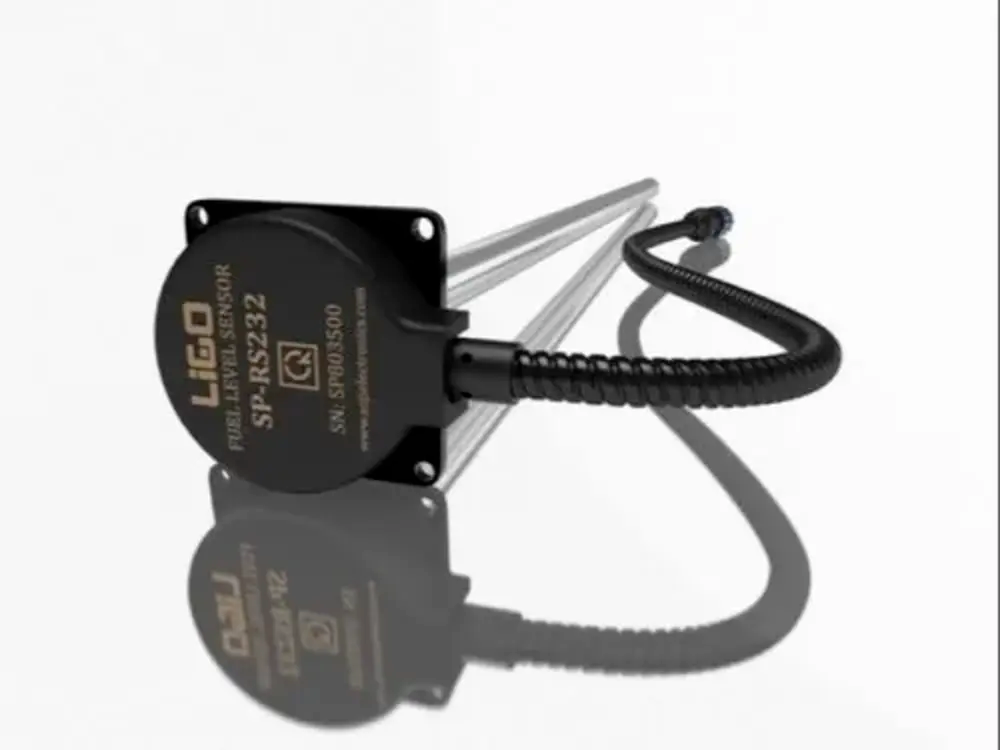 | Level Sensor Ligo fuel sensor for monitoring Diesel and Petrol level in vehicle fuel tanks and DG sets. View product → |
 | Level Transmitter Hydrostatic liquid level transducers and transmitters with flush diaphragm is designed fora wide variety of level measurement applications. View product → |
 | Level Transmitter Ultrasonic Level Sensor is a non-contact ultrasonic continuous level measurement product based on sound technology. View product → |