A tank reading becomes remote when the measurement is taken at the vessel but shown or used somewhere else. By the end, you will be able to trace the signal from liquid surface to display or control system, compare the main technologies, and check whether an installation will produce a trustworthy reading.
Key takeaways
- Remote means the display is separate from the tank sensor.
- Compare mechanical, wired, fieldbus, HART, and wireless connections.
- Check tank size, liquid properties, pressure, temperature, and hazardous-area needs.
- Validate the signal loop before linking level data to control actions.
What does “remote” mean in a tank level indicator?
A remote tank level indicator is a system whose sensing element is mounted at or connected to the tank while the indication appears elsewhere. “Remote” does not necessarily mean wireless: the connection may use a mechanical linkage, 4–20 mA loop, fieldbus, HART, or a wireless transmitter.
Common arrangements include:
- A mechanical pointer or gauge mounted where you can see it away from the vessel.
- A tank sensor connected to a local digital display, such as a panel near the tank.
- A transmitter sending level data to a PLC, SCADA system, building-management system, or remote dashboard.
The measurement chain works in this order:
- Liquid movement changes a float position or changes the reflected ultrasonic distance from the sensor to the liquid surface.
- The sensing element converts that position or distance into an electrical signal.
- A receiver scales the signal into level, volume, or an alarm using the configured range and units.
Continuous measurement produces a changing remote level value as the liquid rises or falls. A side-mounted level switch does something different: it changes state at one set height for pump control or an alarm. It does not provide a continuously changing remote level value.
An indicator outside the tank also does not automatically provide overfill protection; a separate high-high sensor and shutdown path may be required.
How do the main remote level technologies compare?
A remote tank level indicator trades simplicity for signal range, installation flexibility and resistance to process conditions. The comparison is easiest by asking what each technology actually measures.
| Technology | Working principle | Practical trade-offs |
|---|---|---|
| Float-and-board | A float follows the liquid; a cable or tape moves an external board. | Simple visual indication with little electronic complexity; needs mechanical access and can jam. |
| Magnetic gauge | A float moves magnets inside a chamber, turning an external scale or flags. | Clear local reading without tank entry; chamber valves and float movement need maintenance. |
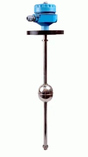
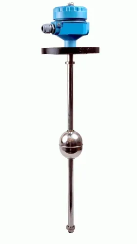
| Float transmitter | Float travel drives a potentiometer, reed chain or encoder that produces a remote electrical signal. | Adds PLC or display integration, but moving parts and sticking remain concerns. |
| Hydrostatic transmitter | Infers level from pressure, approximately ΔP = ρgh. | Gauge pressure suits open tanks; differential pressure compares bottom pressure with vapour-space pressure in closed or pressurised tanks. Density changes, entrained gas and temperature create errors. |
| Ultrasonic transmitter | Calculates distance from acoustic time of flight. | Non-contact, but foam, condensation, vapour, dust, agitation and temperature effects can weaken or redirect the echo. |
| Radar | Calculates distance from electromagnetic travel time. | Avoids liquid-density dependence, but foam, turbulence, antenna buildup, weak dielectric response and false echoes remain concerns. |
Guided-wave radar sends the pulse along a probe, helping in vessels with obstructions or difficult vapour conditions. Probe coating, conductive deposits, turbulence and contact with internal metalwork can corrupt the return, so a free-space radar installation is not automatically interchangeable.
Which technology suits a difficult or hazardous tank location?
Choose a mechanical remote gauge when power, programming and electronic maintenance are undesirable and an operator can see the indication. Choose an electronic transmitter when the reading must reach a PLC, SCADA system, building-management system or remote dashboard. For an inaccessible, buried, elevated or distant tank, confirm that inspection and signal wiring remain maintainable.
| Option | Check before choosing | Suitable location |
|---|---|---|
| Mechanical remote gauge | Visible indication; no power or programming | Operator viewing point |
| Hydrostatic transmitter | Stable liquid density and pressure reference | Known, consistent liquid |
| Ultrasonic transmitter | Gas temperature, vapour, foam, condensation and agitation | Open, calm tank |
| Radar transmitter | Dielectric response, antenna clearance, buildup and obstructions | Closed or difficult tank |
For a closed tank, verify the high- and low-pressure reference arrangement. Wet legs, dry legs, impulse tubing and remote seals can create offsets through condensation, evaporation, trapped gas, plugged lines, unequal temperatures, wet-leg density changes or capillary temperature gradients.
Use this checklist when comparing an industrial instrument from Filpro Sensors Pvt Ltd or another supplier:
- Qualify the complete hazardous-area chain: sensor, wiring, barrier or isolator, receiver and installation method.
- For intrinsic safety, match entity parameters and use approved associated apparatus with compliant wiring.
- If the indicator controls a pump or valve, check filtering, update time, damping and the response to a failed or frozen signal.
Related products
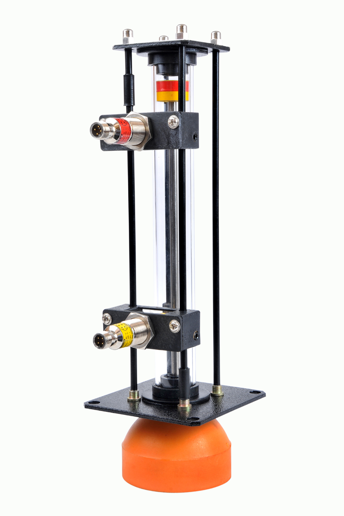 | Level Gauge Oil Level Indicator is designed to indicate the coolant and hydraulic oil level inside the tank with a visual indicator above the tank. View product → |
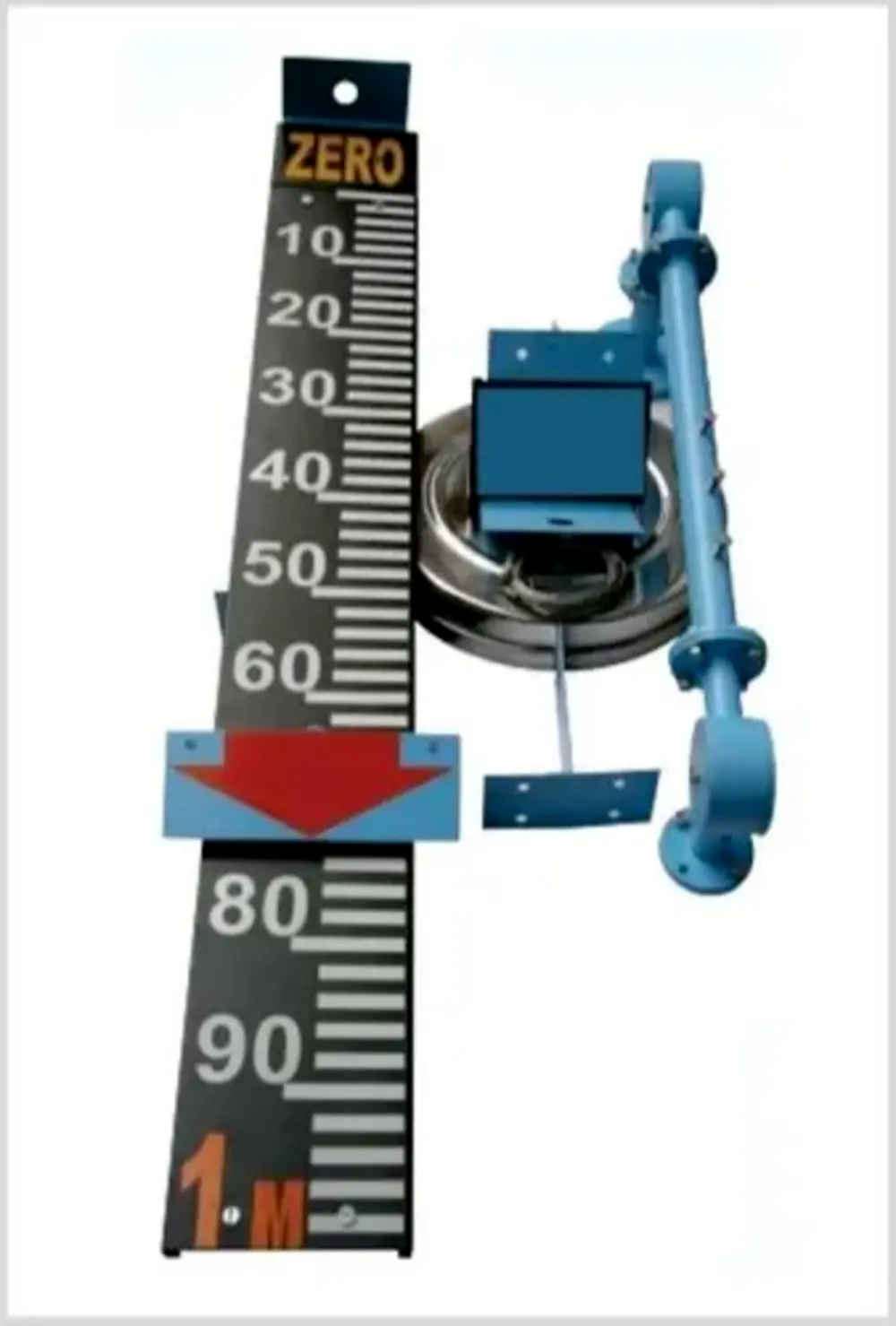 | Level Indicator The Float & Board Level Indicators consists of a float connected to a pointerthrough a rope via a set of pulleys. View product → |
How do you check whether the sensor fits the tank?
Check fit by calculating the usable measuring range before ordering, not by matching the probe length to tank height.
- Measure the tank height from bottom datum to roof, the mounting-point elevation, nozzle position and nozzle length, maximum fill level, and required bottom clearance.
- Define the lowest liquid surface as the tank bottom plus the required clearance. Define the highest surface as the maximum fill level.
- Calculate the required span from the sensor mounting point to both surfaces. Subtract the sensor’s inactive or dead zones from its stated probe or measuring length; the remaining range must cover that span.
- For ultrasonic or radar instruments, measure from the transducer face or antenna to the maximum liquid level. Keep the manufacturer’s specified near-zone clearance; a surface inside that zone can produce an invalid reading.
- Check the nozzle, roof angle, internal beams, ladders, agitators and tank outlet. Any obstruction can block a radar or ultrasonic path, while an outlet can create turbulence or an unexpectedly low local level.
Level height is not automatically volume. A vertical cylinder is nearly linear, a horizontal cylinder has a curved height-to-volume relationship, and a rectangular tank is usually linear; an irregular vessel needs a strapping table or calibrated level-to-volume map. Specify whether the display shows millimetres, litres, percentage or mass, and document the conversion table used.
How does the signal become a reliable remote reading or control action?
A remote tank level indicator becomes dependable when the transmitter, cable, receiver and control logic are specified as one measurement loop. A live signal alone does not prove that the level measurement is valid.
1. Use 4–20 mA for a robust current loop over substantial cable runs. Confirm the transmitter’s configured lower range value, upper range value and engineering units, then enter the same values in the indicator, PLC or SCADA input.
Check loop power and receiver scaling: 4 mA must represent the same low value at both ends, and 20 mA must represent the same high value.
2. Treat 0–5 V and 0–10 V as voltage signals, not interchangeable current loops. Match the receiver’s input impedance, grounding arrangement and permitted cable length; voltage drop, electrical noise and ground differences can corrupt a long run.
3. Do not substitute RS-232 for RS-485. RS-232 is generally point-to-point; RS-485 supports a bus. Specify Modbus RTU or the supplier’s proprietary protocol, device addressing, baud rate and termination requirements.
4. Agree how the receiver handles fault currents. Under NAMUR NE 43 conventions, ≤3.6 mA and ≥21.0 mA indicate failure-information regions, so configure alarms and control responses consistently.
5. Set filtering, update time and transmitter damping with pump or valve response in mind. Excessive damping can delay protection, while a failed or frozen value needs its own timeout alarm.
A display is not overfill protection. Where the risk assessment requires it, add an independent high-high sensor, alarm path or shutdown.
Frequently asked questions
What does “remote” mean in a tank level indicator?
Remote means the sensing element is mounted at or connected to the tank while the level indication appears elsewhere. The connection can be mechanical, wired, digital, or wireless.
How do the main remote level technologies compare?
Mechanical systems use a physical linkage, while 4–20 mA systems send an analogue signal. HART adds digital diagnostics, fieldbus supports networked communication, and wireless systems avoid signal cables.
Which technology suits a difficult or hazardous tank location?
Choose based on access, cable routes, power availability, interference, maintenance needs, and the tank’s hazardous-area classification. Confirm that every installed device has the required area approval.
How do you check whether the sensor fits the tank?
Match the sensor to the tank connection, measuring range, liquid compatibility, pressure, temperature, density, foam, agitation, and installation clearance.
How does the signal become a reliable remote reading or control action?
The sensor measures level, a transmitter converts it into a defined output, and a display, PLC, or control system scales and checks that signal before taking action.
Related products
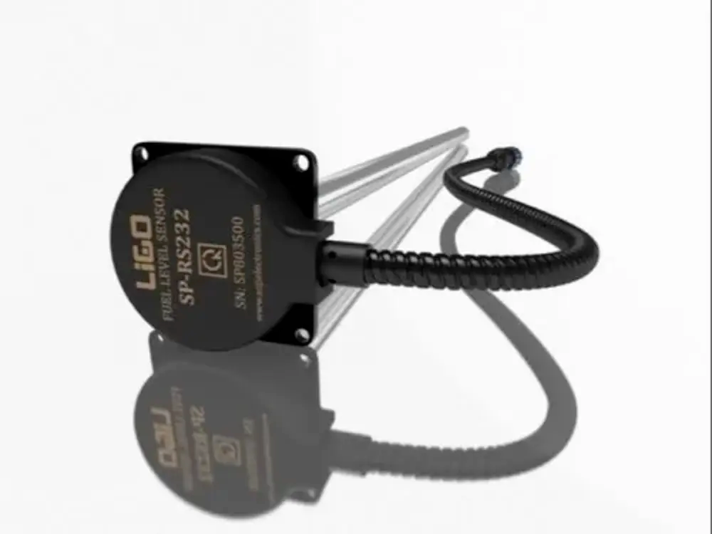 | Level Sensor Ligo fuel sensor for monitoring Diesel and Petrol level in vehicle fuel tanks and DG sets. View product → |
 | Level Transmitter Float Level Transmitters Are Ideal For Continuous Level Monitoring In Water, Diesel, Chemical And Oils For Accurate Level Measurement. View product → |
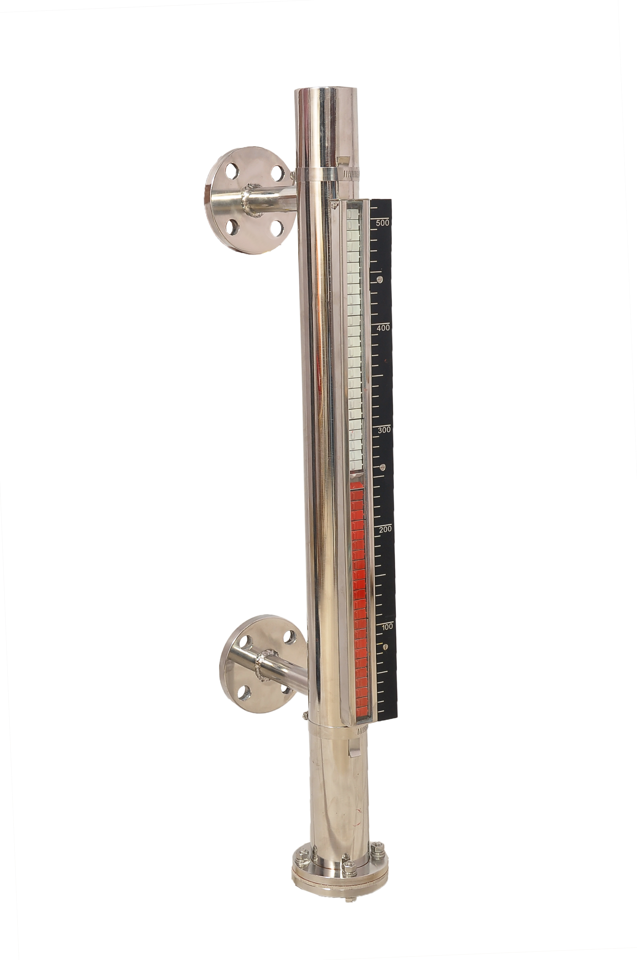 | Level Gauge FILPRO offers Magnetic Level Indicator provides clear, high clarity indication of liquid level. View product → |
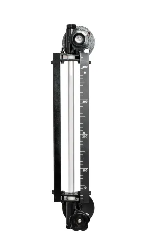
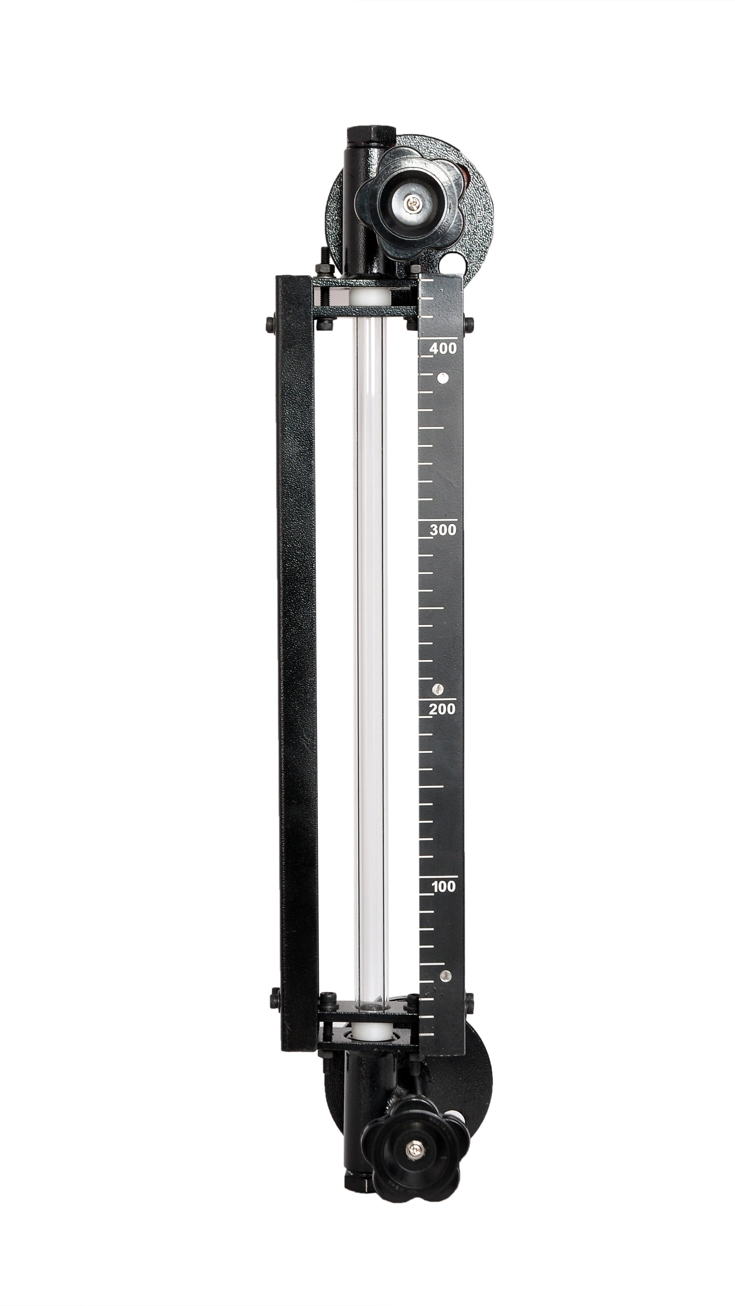
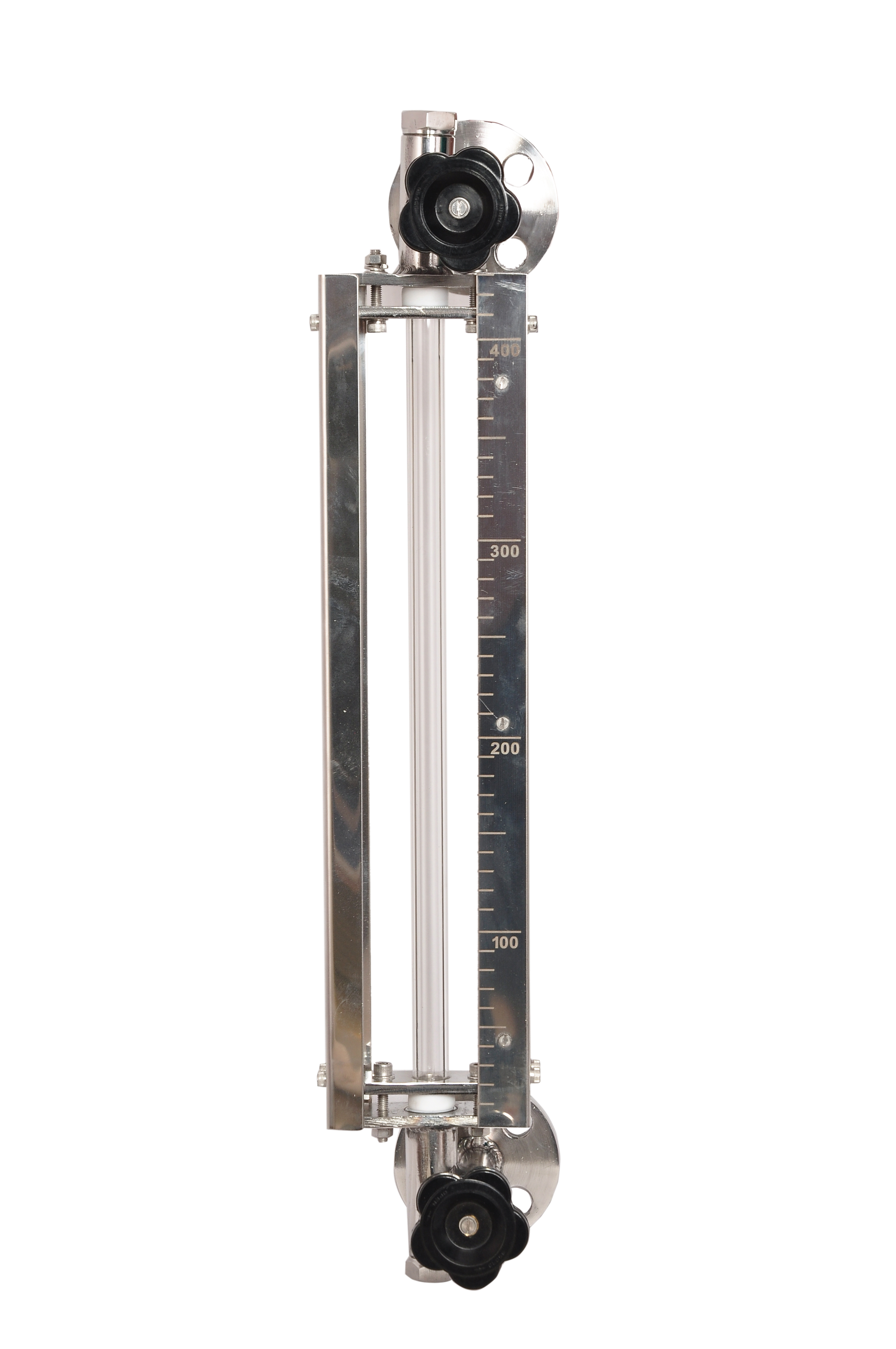 | Level Gauge Tubular Glass Level Indicator is used for visual level indication of liquid in storage and process tanks. View product → |