A capacitive device performs well when the liquid creates a repeatable electrical contrast and the probe has a stable reference. By the end, you will be able to screen capacitive level sensor applications, check whether your vessel supports the method, position the probe correctly, and decide when another technology is safer.
Key takeaways
- Choose capacitance for liquids with a stable dielectric constant.
- Verify signal stability across empty, operating, and full conditions.
- Keep the probe away from walls, agitators, inlets, and buildup.
- Compare capacitance with ultrasonic, hydrostatic, float, and point-switch options.
Which tank and liquid conditions favour capacitance measurement?
Capacitance measurement works best in vessels containing a liquid with a stable dielectric constant and a predictable change between empty and full. A capacitive level sensor measures the capacitance between its probe and a tank wall, ground, or dedicated reference electrode.
Metal tanks simplify the circuit because a grounded wall provides a consistent reference; plastic vessels need a concentric probe, reference electrode, or defined ground path.
| Condition | Why it favours measurement | Practical implication |
|---|---|---|
| Stable water-based liquid | Relative permittivity is roughly 80 at room temperature, creating a large signal against air | Strong capacitive level sensor applications and reliable continuous level measurement |
| Mineral oil or hydrocarbon | Relative permittivity is often only 2–3, so the capacitance change is small | Control probe geometry, cable length, fittings, and calibration tightly |
| Nonmetallic tank | The vessel does not provide a dependable reference electrode | Add a dedicated electrode or concentric probe |
Compact probes and no moving parts suit confined tanks and reduce mechanical failure points. Low-dielectric solvents and hydrocarbons need calibration with the actual liquid at empty and full, or at other known levels.
Reject or recheck the application when these conditions can move the reading without moving the level:
- Concentration, moisture, temperature, formulation, or product composition changes
- Probe coating, tank internals, nozzle dimensions, grounding, or cable routing changes
- Stray capacitance from fittings, buildup, or adjacent metal approaches the liquid signal
How do you verify that the liquid will produce a stable signal?
Verify stability by testing the actual liquid with the intended probe, vessel and reference arrangement before purchase or installation. A nominal dielectric constant is not enough: concentration, temperature, formulation and batch variation can change the signal.
- Classify the product as conductive liquids, non-conductive liquids, or variable between batches. Record its dielectric constant, or obtain measurements across the full operating concentration and temperature range.
- Compare the liquid’s dielectric response with air and with the tank wall or reference electrode. Then test empty, intermediate and full conditions using the actual probe, product, vessel material and expected installation geometry.
- For conductive liquids, specify an intact insulating coating on the sensing electrode. Without it, the liquid can short the electrode to the vessel or another electrode, producing a conductivity-dependent reading or a continuous-wet indication after coating damage.
- For non-conductive liquids in plastic tanks, use a concentric probe, dedicated reference electrode or another defined electrical reference. A nearby fitting, cable or support is not a reliable substitute.
| Liquid or condition | What to verify | Decision |
|---|---|---|
| Single liquid | Repeatable dielectric contrast between air and liquid across the operating range | Suitable when empty, intermediate and full signals remain distinct |
| Variable batches | Measured response at minimum and maximum concentration and temperature | Test each limiting condition before approval |
| Liquid-liquid interface | Repeatable dielectric contrast and a sharp boundary | Suitable for a defined interface |
| Emulsion or rag layer | Gradual or unstable dielectric transition | Require application testing; do not assume a precise interface signal |
Calibrate continuous instruments against actual empty and full, or other known, process conditions. Recheck calibration after changing formulation, coating, probe geometry, tank internals or grounding.
Where should the probe sit, and what should surround it?
Probe placement starts with clearance. Keep the sensing element away from the tank wall, agitator, inlet stream, heating coil, internal baffle and nozzle edge; each can become part of the electrode geometry and produce a level-dependent error or false full signal. Keep it away from surfaces where foam and buildup collect.
There is no universal clearance: use the instrument maker’s geometry limits.
- Choose a calmer mounting location when splashing, vortexing or agitation makes the point output chatter.
- Use a stilling well when the vessel cannot provide a calm zone.
- Add hysteresis or a time delay for pump control or overfill trips when the control logic permits it.
- Confirm tank grounding, cable routing, seals, process connection and hazardous-area protection, including intrinsic-safety parameters where required.
A bare probe suits a non-conductive liquid when the electrode must couple through the product. A conductive liquid can electrically short a bare electrode, so compare these options before installation:
| Option | What it means | When it applies |
|---|---|---|
| Bare probe | Exposed sensing electrode | Non-conductive liquid and compatible tank geometry |
| PTFE insulated probe | Electrode covered by an intact PTFE layer | Conductive liquid, including high-temperature tank service |
Insulation protects the electrode, but deposits on the sleeve still add dielectric loading. Cleaning can change the apparent signal, so recalibrate afterward. Test persistent foam with the actual process; liquid-filled foam can trigger premature switching.
How does capacitance compare with ultrasonic, hydrostatic, float, and point switches?
Capacitance suits continuous measurement or point switching when the product’s dielectric behaviour and the probe environment remain controlled. Choose it when a compact wetted probe and no moving parts matter, including detection through a nonmetallic process wall.
| Method | What it measures | Choose it when |
|---|---|---|
| Capacitive | Dielectric change around a probe | The product and probe environment are stable; continuous level or point switching is required |
| Ultrasonic | Echo from the liquid surface | Non-contact ultrasonic level measurement has a clear path and the surface, vapour space, foam and tank geometry support a reliable echo |
| Hydrostatic | Pressure from the liquid column | Density stays stable and a pressure connection with a flush diaphragm is acceptable |
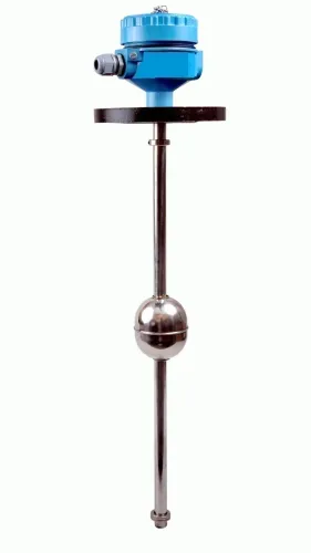
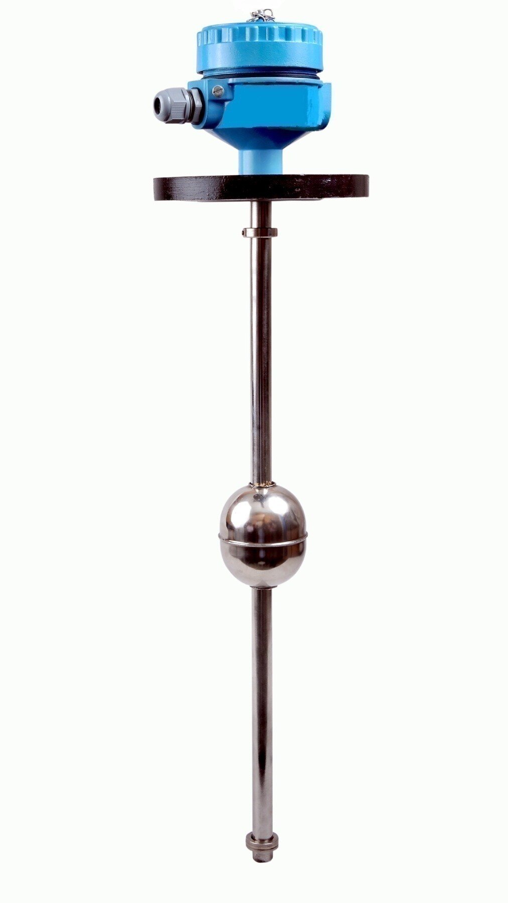
| Float transmitter | Mechanical float position | A moving element suits water, diesel, chemicals or oils |
| Point-level switch | Presence or absence at one height | You need a high-high alarm or low-level protection independent of the continuous transmitter |
Do not make a continuous transmitter carry every safety function. A dedicated point-level switch or independent alarm channel gives separate high-high protection, while low-level pump protection can act before the tank reaches a damaging condition.
Persistent foam, sludge, crystallisation, polymer coating or severe composition changes weaken the case for capacitance. Test the actual product and process, or choose another technology, instead of relying on an optimistic specification. A trial is particularly important when buildup can change the probe’s electrical environment.
What should you document before approving a capacitive installation?
Before approving a capacitive installation, require supplier documentation that turns the proposed capacitive level sensor applications into a commissioning checklist.
- Record the liquid name, dielectric data or a test sample, conductivity, solids content, foam behaviour, and emulsion risk.
- Record the operating temperature and pressure range, cleaning chemicals, cleaning cycle, and tank material.
- Confirm internal metalwork, probe length, insulation material, reference arrangement, and hazardous-area classification.
- Specify the empty and full calibration points, including the vessel conditions used to establish each point.
Ask how the instrument handles coating, sludge, crystallisation, and a changed formulation. Coating sensitivity matters because deposits can make a conventional sensor indicate level after the liquid has fallen. Active-shield or RF-admittance designs reduce deposit error; they do not make buildup harmless.
| Change | Calibration consequence | Required action |
|---|---|---|
| Formulation change | Dielectric response can shift | Repeat calibration with the new liquid |
| Probe coating or sludge | Apparent level can remain high | Inspect, clean, and recalibrate |
| Tank internal or grounding change | Electrode geometry changes | Recheck signal margin and calibration |
Calibration must use the actual liquid and vessel, at confirmed empty and full points, then be repeated after any listed change. Include the cleaning plan and a fallback technology if the process changes. Filpro Sensors Pvt Ltd is one supplier to ask for this application-specific documentation rather than selecting from a catalogue description alone.
Related product
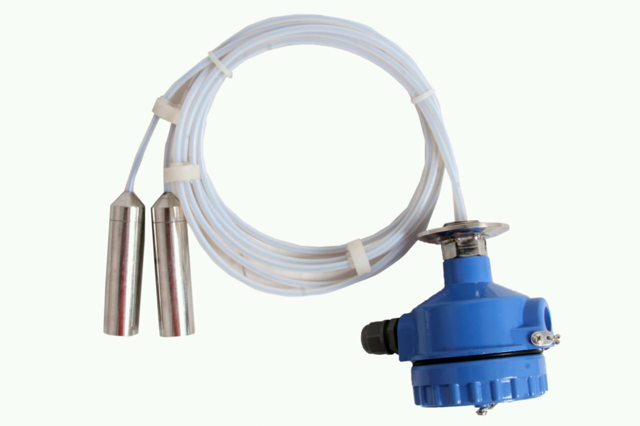 | Level Transmitter can be used for conductive as well as non conductive liquids. View product → |
Frequently asked questions
Which tank and liquid conditions favour capacitance measurement?
Capacitance works best when the liquid has a stable dielectric constant and produces a predictable change between empty and full.
How do you verify that the liquid will produce a stable signal?
Check the liquid’s dielectric behaviour across its operating temperature, composition, moisture content, and expected level range, then test empty, operating, and full conditions.
Where should a capacitive probe sit in the tank?
Place the probe where it represents the true level and keep it away from walls, agitators, inlets, outlets, and material that could create buildup.
How does capacitance compare with other level technologies?
Compare capacitance with ultrasonic, hydrostatic, float, and point-switch devices based on liquid properties, tank geometry, contact requirements, buildup, and whether you need continuous or point-level measurement.
What should you document before approving a capacitive installation?
Record the liquid properties, temperature and composition range, tank and probe geometry, grounding arrangement, installation location, test results, calibration settings, and cleaning requirements.