A flanged gauge is useful when you need removable local level indication on a vessel or external chamber, but the flange must match the nozzle, gasket, bolting and pressure-temperature conditions as a complete joint. By the end, you will be able to decide whether flanged, threaded, welded, glass, magnetic or electronic equipment fits the service and verify the connection before ordering.
Key takeaways
- Match the gauge flange rating, size and facing to the tank nozzle.
- Choose flanges when bolted maintenance access matters more than compact installation.
- Select glass and safeguards for pressure, temperature and fluid hazards.
- Use magnetic, reflex, transparent or transmitter-based measurement for the process.
What a flanged level gauge actually connects
A level gauge with flange connection is a complete local-indication assembly fitted to a vessel’s process opening. It includes the process flange, gasket, bolts, and a chamber or glass assembly that contains and displays the liquid level.
The tank nozzle is the welded neck on the vessel wall; the flange joins that nozzle to the gauge without cutting or welding during removal.
1. Confirm that the vessel has a standardized flanged tank nozzle and record its nominal size, facing, pressure class, orientation, and bolt pattern. A flanged level gauge can connect directly between two side nozzles, with one connection at the liquid’s lower elevation and the other above it.
2. If the vessel has one suitable nozzle, specify an external chamber level gauge. The chamber mounts beside the tank and connects to upper and lower vessel nozzles; its visible span must extend across the required minimum and maximum operating levels.
3. Check center-to-center spacing, nozzle elevations, alignment, and available clearance before ordering. A matching flange standard does not correct misaligned nozzles, and forced fit-up can transmit pipe strain to the glass or chamber.
The nominal flange size identifies the connection dimensions, not the usable measuring range. The upper and lower connection elevations establish that range, while the flange itself does not improve accuracy.
Also check the complete pressure boundary: a Class 300 flange cannot make a lower-rated glass, valve, gasket, bolt set, or chamber suitable for Class 300 service. Choose this flanged level gauge when you need direct visual indication or local backup at a vessel with a standardized flanged nozzle.
When a flange is better than another connection
A level gauge with flange connection is the stronger choice when the vessel already has a matching flanged nozzle, the service is demanding, or you must remove the gauge without cutting or welding the process connection.
| Option | Practical advantage | Best fit |
|---|---|---|
| Flanged | Removable joint with a gasket and bolted connection | High pressure or temperature, corrosive or hazardous liquid, large connections, strict leak control, or an existing matching nozzle |
| Threaded or screwed | Compact installation with less assembly work | Smaller, lower-risk services where removal and leak containment are straightforward |
| Welded | Permanent, compact connection with no threaded leak path | Fixed installations that are not expected to need gauge removal |
| Side-mounted level gauge | Displays a visible level span beside the vessel | A local sight line is required across the operating range |
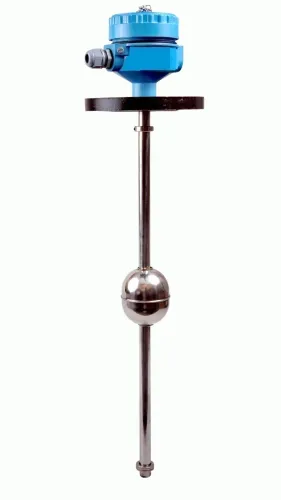
| Top-mounted level gauge | Uses access from above rather than a side nozzle | Tanks where the roof is accessible and a suspended float, probe, or other extended arrangement is acceptable |
Choose a flange when:
- The vessel nozzle and gauge share the same nominal bore, flange standard, pressure class, facing and bolt pattern.
- High pressure, high temperature, corrosive liquid, hazardous liquid, a large connection, or strict leak control makes a threaded joint less attractive.
- Maintenance requires removal without welding or cutting the process line.
Flanged versus threaded level gauge installation takes more work: align the faces, fit a compatible gasket, install the bolts and tighten them in a controlled sequence. Frequent removal is useful only when isolation valves, depressurization, drain or vent provisions, and maintenance access are available. Otherwise, the flange does not solve the maintenance problem.
How to match the gauge flange to the tank nozzle
Match a level gauge with flange connection to the tank nozzle by checking the complete flange geometry, not just the nominal bore. Select the pressure class from the pressure-temperature rating, material group, flange type and design code—not nominal bore alone.
ASME B16.5 covers steel flanges from NPS 1/2 through NPS 24; ASME B16.47 covers larger steel flanges.
| Designation | What to verify |
|---|---|
| ASME B16.5 Class 150 | Use its specific pressure-temperature rating and material group; it is not interchangeable with PN16. |
| ASME B16.5 Class 300 | Higher class does not override a lower-rated gauge component; confirm the complete assembly rating. |
| EN 1092-1 PN16 | Match the EN flange dimensions, facing and pressure-temperature limits; do not assume ASME compatibility. |
| EN 1092-1 PN40 | Confirm the PN40 rating at the operating temperature and the exact mating nozzle standard. |
Before purchase, obtain the nozzle drawing and check:
- Nominal bore, facing type, such as raised face, flat face or ring-type joint, bolt-hole circle, hole count and bolt diameter
- Gasket type, face finish, bolt length, clearance and access for tightening
- For two-connection gauges, nozzle center-to-center spacing, elevations, orientation and alignment; forced fit-up creates pipe strain
- Gauge chamber, glass, valves, bolts, gasket and sight-glass parts; the weakest pressure boundary limits the complete assembly
Use metallic pipe-flange gaskets specified under ASME B16.20 and assemble and tighten the joint using ASME PCC-1 practices. A Class 300 process flange cannot make a lower-rated glass or chamber suitable for Class 300 service.
Choose materials, glass and safeguards for the process
Select wetted chamber, float, glass, seals, flange and gasket materials from the actual liquid chemistry, concentration, density, viscosity, solids content, pressure, and minimum and maximum metal temperature. Check both liquid and vapour compatibility; a corroded or sticking float gives a false level. Rate the complete assembly at every temperature and pressure, not only normal operation.
Rapid heating, cooling, unequal heating, thermal cycling and cold-service frosting can cause leakage or glass damage.
| Option | Best choice | Check before selection |
|---|---|---|
| Reflex glass level gauge | Clean liquid needing a strong liquid-vapour distinction | Confirm the liquid will not coat or obscure the optical grooves |
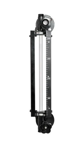
| Transparent level gauge | Colour, interface, suspended solids or two-phase behaviour must be observed | Confirm glass protection and visibility through the full range |
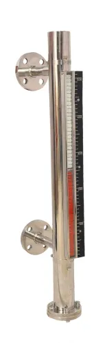
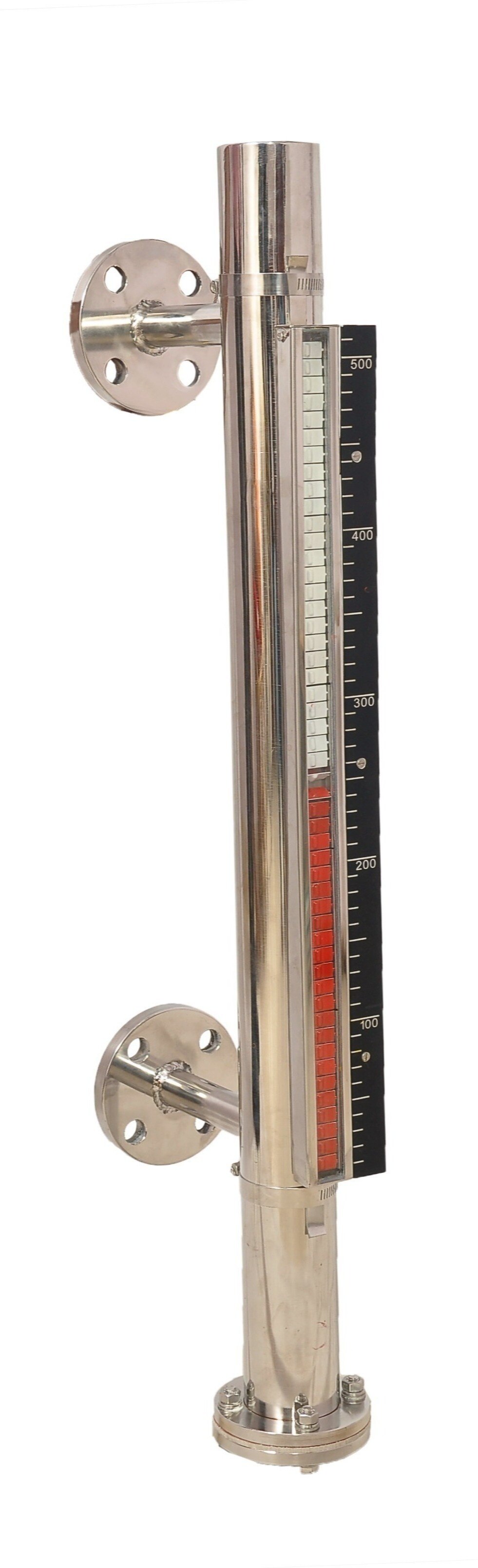
| Magnetic level gauge with flange connection | Toxic or corrosive liquid requires a sealed visual chamber | Match the float to density, viscosity, temperature, pressure and solids; verify the chamber pressure rating |
For hazardous, high-pressure or high-temperature service, specify isolation valves, a drain or vent, and guards or shields against broken glass. Automatic ball-check shutoff devices can limit discharge after glass failure, but they do not replace isolation, depressurization or a written maintenance procedure.
Check the weakest pressure boundary: a Class 300 flange does not make a lower-rated chamber, valve, glass, bolt set or gasket suitable for Class 300 service.
Select the measurement method for the job
Select the measurement method from the information you need, not from the connection alone. A level gauge with flange connection provides local indication; choose a separate control instrument when the process needs remote data.
| Option | What it provides | When to choose it |
|---|---|---|
| Sight glass | Direct visibility with limited automation | Choose a flanged tubular or transparent glass gauge when liquid color, interface, suspended material or two-phase behavior matters and the process can safely accommodate the glass assembly. |
| Magnetic gauge | Local indication through a sealed chamber | Choose a flanged magnetic level gauge when operators need visual indication with reduced direct exposure to a toxic, corrosive or hazardous liquid. |
| Electronic level transmitter | Continuous remote measurement, trends, alarms and diagnostics | Choose it for control-system input or closed-loop control. Keep a local gauge for verification, not as a replacement. |
| Point-level switch | A discrete high-level or low-level signal | Choose it for an alarm, pump interlock or shutdown when continuous measurement is unnecessary. |
A sight glass gives direct visibility but limited automation. A magnetic gauge isolates the indicator from the liquid, while its process chamber remains pressurized. An electronic level transmitter adds signal and diagnostics at the cost of power, configuration and calibration.
Before selecting the assembly, ask a manufacturer such as Filpro Sensors Pvt Ltd to confirm:
- Nozzle dimensions
- Pressure-temperature rating of the complete assembly
- Wetted materials
- Gasket specification
- Isolation arrangement
- Visible span
- Separate control-system requirement
Related product
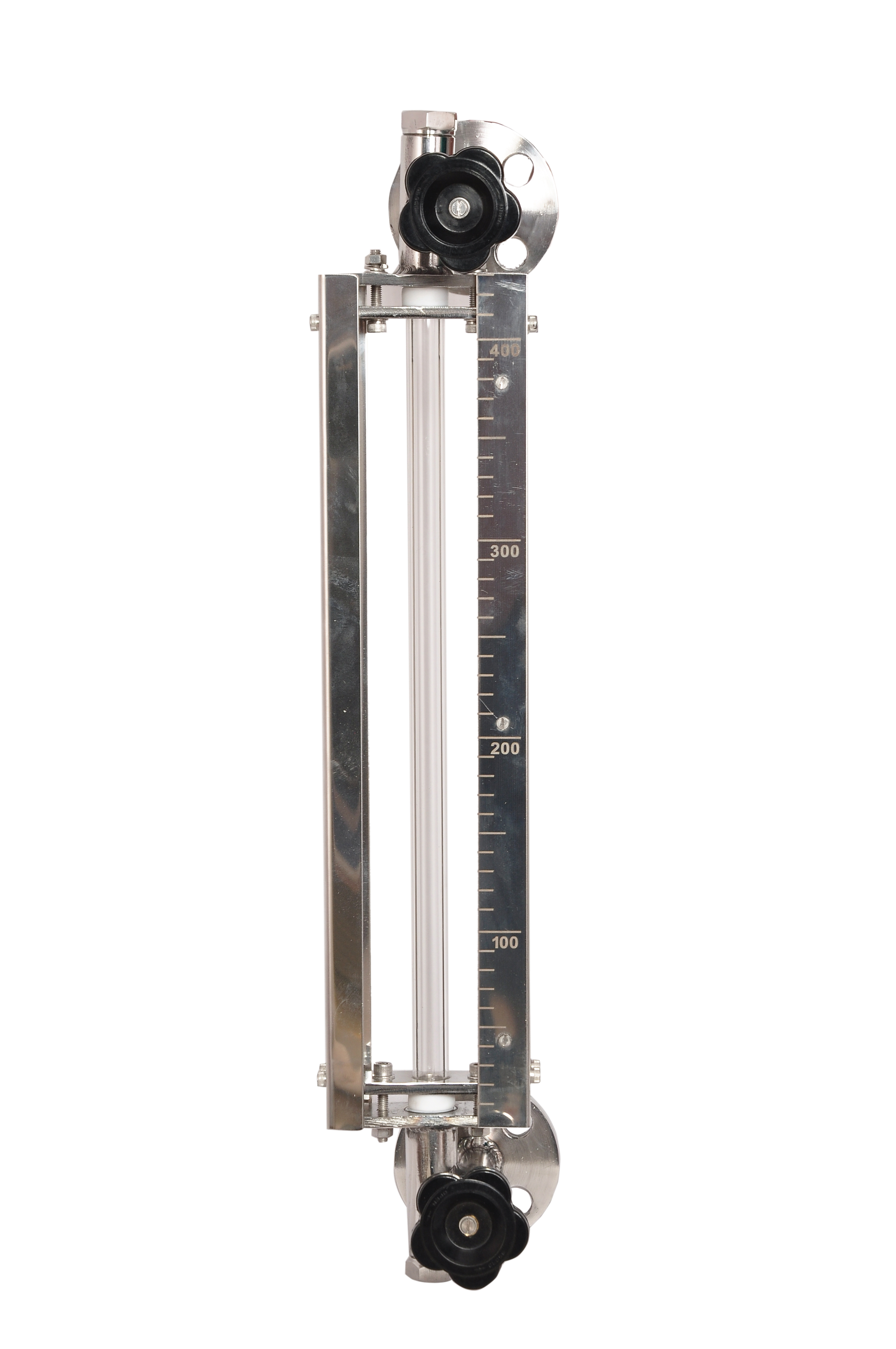 | Level Gauge Tubular Glass Level Indicator is used for visual level indication of liquid in storage and process tanks. View product → |
Frequently asked questions
What does a flanged level gauge connect to?
It connects a local-indication chamber or glass assembly to a vessel’s process nozzle using matching flanges, a gasket and bolts.
When is a flange connection better than another connection?
Choose a flange when you need a strong bolted joint, easier removal for maintenance or compatibility with an existing flanged tank nozzle.
How do you match the gauge flange to a tank nozzle?
Match the nominal size, pressure class, flange facing, bolt-hole pattern, gasket dimensions and material requirements of both flanges.
How do you choose glass and safeguards for a level gauge?
Select reflex or transparent glass for the viewing need, then specify materials, temperature and pressure ratings, shields and isolation valves for the process hazards.
Which level measurement method should you select?
Use a direct glass gauge for local visual reading, a magnetic gauge for safer external indication, or a transmitter when remote monitoring and control are required.