A visible number on a tank does not guarantee that the measurement is accurate, safe, or useful to your control system. You will be able to match the sensing principle, display and signal architecture to the liquid and vessel, then specify an installation that avoids false readings and maintenance problems.
Key takeaways
- Use a transmitter for continuous level; add a separate switch for point-level alarms.
- Match radar, ultrasonic, hydrostatic or guided-wave technology to the liquid and tank.
- Specify the display range, output signal, power supply and hazardous-area requirements.
- Verify the displayed level against a measured reference after installation.
Define what the display and transmitter must do
Choose a tank level transmitter with display when you need continuous level measurement and a readable local value; it is not automatically a point-level switch or a complete overfill protection system.
Define the required function before comparing instruments:
- Use continuous measurement when operators or a control system need the changing level, volume, mass, percentage, or distance. Specify whether the local display is an integral LCD, LED, analog indicator, remote panel meter, or PLC/HMI value.
- Use a point-level switch when you need a discrete “level reached” signal, such as low-level pump protection or a side-mounted high-level alarm. A switch is the better choice when one dependable trip point matters more than the level between those points.
- Specify a high-high shutdown as a separate, independently tested safeguard when overfill could cause injury, release, or equipment damage. The transmitter display normally repeats the measured variable; it does not provide an independent shutdown path.
- Confirm that the displayed engineering unit and the 4–20 mA output are correct. Ask whether the display can be configured independently from the output.
- Match the measuring principle to the tank: hydrostatic instruments need the actual liquid density; ultrasonic and radar instruments need clear sight or antenna conditions; floats and capacitance probes need suitable geometry and liquid properties.
- Check the usable range, blocking distance, nozzle, obstructions, fill stream, lowest level, and display access. Tank height alone is not the measuring range.
For hazardous locations, match the transmitter, display, barrier, cables, grounding, and area classification. “Intrinsically safe” is not the same protection concept as explosionproof or flameproof.
Match the measurement principle to the tank and liquid
Match the sensing principle to the tank geometry, liquid properties and vapour space—not to the display format. An integral LCD, LED, remote panel meter or PLC/HMI only shows the measured variable; it does not make a weak measurement reliable.
| Option | What it means | When it applies |
|---|---|---|
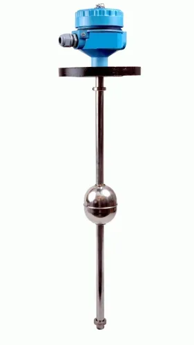
| Float level transmitter | A float follows the surface and drives a magnetic, mechanical or electronic output | Clean, low-viscosity liquids with limited turbulence; avoid it where solids, wax or sticky product can jam movement |
| Hydrostatic level measurement | Pressure at the tank bottom is converted to liquid height | Vented tanks with stable density; configure the transmitter for actual density when density changes, or the displayed level will be wrong |
| Ultrasonic level transmitter | Sound travels to the surface and returns as an echo | Open or low-pressure tanks with a calm surface and known vapour acoustics; vapour, temperature gradients, foam and condensation can weaken the echo |
| Radar level transmitter | Microwave energy measures the surface distance | Pressurised, hot, dusty or turbulent tanks; confirm the specified minimum dielectric constant, antenna and range for low-dielectric liquids |
| Capacitance probe | Capacitance changes as the liquid covers the probe | Conductive or stable-dielectric liquids; buildup on the probe can create a false level |
Choose non-contact radar over ultrasonic when vacuum, vapour composition or gas temperature changes distort sound propagation. A stilling well can calm turbulence, but plugged holes, condensation and product buildup can isolate its level from the tank.
For a high-high alarm, use an independently tested level switch and shutdown path; the display transmitter is not automatically an overfill safeguard. A side-mounted switch is often the better choice for a single point alarm.
Specify the display, output and signal path
Choose a transmitter whose local display, electrical output and signal path use the same defined variable and engineering units. An LCD level display should show level, volume, distance, mass, percentage or a diagnostic state—whichever you need—and indicate the unit clearly. Confirm whether its scaling can be configured independently from the 4–20 mA output.
| Arrangement | Signal path | Selection check |
|---|---|---|
| Integral LCD level display | Transmitter display plus 4–20 mA to PLC or HMI | Confirm display readability, backlight, viewing angle and access during maintenance |
| Remote panel indicator | Transmitter output wired to a separate display | Check cable distance, loop power, input compatibility and matching calibration |
| PLC or HMI display only | Transmitter output becomes the displayed value | Verify PLC scaling, alarm limits, decimal resolution and loss-of-signal behaviour |
Use 4–20 mA for a robust analogue signal over industrial cable runs; define whether 4 mA and 20 mA represent zero and full scale, and record the fault current setting. Choose 0–10 V only when the receiving equipment accepts voltage input and the cable installation limits noise and voltage drop.
HART communication adds digital configuration, measured-value verification and diagnostics to a 4–20 mA loop. Confirm that the transmitter, barrier or isolator, PLC card and handheld communicator pass HART signals; otherwise calibration changes can differ between the local display and control system.
Specify the reference point, range, damping, units, display resolution, output failure action and commissioning method in the purchase documents. A displayed value is not an independent high-high overfill safeguard.
Design the tank level transmitter installation around the vessel
Design the tank level transmitter installation around the vessel, not only the instrument. Establish the transmitter’s reference point, nozzle height and internal projection before selecting the measuring range. Leave the specified blocking distance or dead zone below the reference point, and include the nozzle, antenna, upper internals and lowest required process level in the calculation.
Choose the mounting position using these checks:
- Keep a radar antenna or ultrasonic sensor away from the filling stream, agitator, heating coil, ladder and tank wall; use false-echo mapping during commissioning when reflections remain.
- Use top-entry mounting when the roof provides a clear vertical path. Use side-entry mounting only when the sensor’s reference point, insertion length and process connection suit the vessel.
- Fit a stilling well or bypass chamber when turbulence prevents a stable reading, then inspect equalization holes for plugging, condensation and product buildup.
- Keep remote-seal capillaries short and route them together; unequal temperatures or mounting the transmitter above or below the vessel can shift the zero and response.
- Protect the instrument from condensation, washdown, extreme heat, vibration and corrosive vapour with the specified enclosure and mounting hardware.
Wire through the documented cable-entry arrangement, bond or ground the instrument as specified, and separate signal wiring from motor and variable-frequency-drive cables. Provide an isolation point where maintenance staff can work without entering the vessel.
Place the local display where operators can read it from a safe walkway. Leave clearance to remove the cover, inspect terminals and calibrate the transmitter; a correct measurement is useless when access requires climbing onto the tank.
Compare specifications, then verify the reading on site
Compare supplier documents against the actual tank, then witness the reading before acceptance. Check that the drawing identifies the transmitter reference point, nozzle dimensions, orientation, cable entry, grounding or bonding, display access and maintenance clearance. A stated measuring range is usable only after subtracting blocking distance, nozzle effects, upper internals and the lowest required level.
| Check | Supplier document | On-site acceptance test |
|---|---|---|
| Transmitter accuracy | Accuracy, repeatability, drift and response time at stated conditions | Compare the display and 4–20 mA value with a calibrated reference at known levels |
| Process limits | Process temperature and pressure ratings for the sensor, seal, connection and wetted materials | Confirm the installed assembly matches the liquid and cleaning chemicals |
| Range | Reference point, dead zone and minimum usable level | Fill or simulate levels across the operating span; verify both alarm limits |
| Electrical load | Complete loop-load calculation at minimum supply voltage, including cable, barriers and isolators | Measure loop voltage and current with every series device connected |
| Installation | Nozzle, antenna or probe dimensions and grounding instructions | Check orientation, obstruction clearance, cable termination and safe display visibility |
For a float or hydrostatic proposal from Filpro Sensors Pvt Ltd, ask for the exact reference point, calibration method and stated accuracy under your tank conditions rather than accepting a catalogue range.
- Record the displayed level, output current and reference level at low, mid and high points.
- Repeat one point after stabilisation; investigate drift, turbulence or density effects.
- Reject the installation if the display cannot be read safely or the loop fails under minimum supply voltage.
Related products
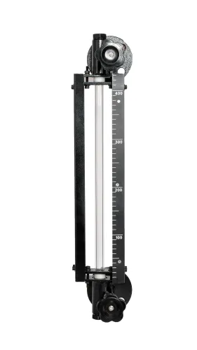
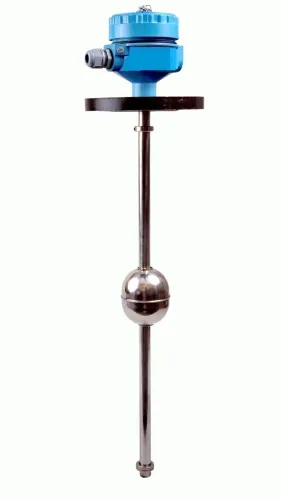
 | Level Transmitter Float Level Transmitters Are Ideal For Continuous Level Monitoring In Water, Diesel, Chemical And Oils For Accurate Level Measurement. View product → |
 | Level Sensor Atex approved Float Level Transmitter : Over All Length: 300mm to 5000mm Input: 16V DC to 30V DC Output: 4-20mA / 0-10V DC Resolution: 5mm / 10mm... View product → |
Frequently asked questions
What must a tank level transmitter with display do?
It must measure continuous liquid level, show a readable local value and send a dependable signal to your control system. It does not replace a point-level switch or a complete overfill protection system.
Which measurement principle fits my tank and liquid?
Choose radar for demanding tanks and vapours, ultrasonic for suitable open or vented tanks, hydrostatic transmitters for compatible liquids with stable density, and guided-wave radar when a probe can be installed in the vessel.
What should I specify for the display and signal path?
Specify the display units and range, 4–20 mA or another required output, HART or communication needs, power supply, alarm handling and the cable route to the control system.
How do I plan a tank level transmitter installation?
Check the nozzle location, obstruction clearance, liquid turbulence, mounting orientation, process temperature and pressure, access for maintenance, grounding and hazardous-area requirements before selecting the instrument.
Related products
 | Level Transmitter Hydrostatic liquid level transducers and transmitters with flush diaphragm is designed fora wide variety of level measurement applications. View product → |
 | Level Transmitter Ultrasonic Level Sensor is a non-contact ultrasonic continuous level measurement product based on sound technology. View product → |
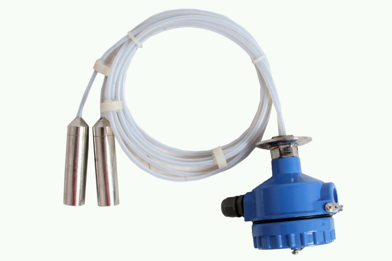 | Level Transmitter can be used for conductive as well as non conductive liquids. View product → |
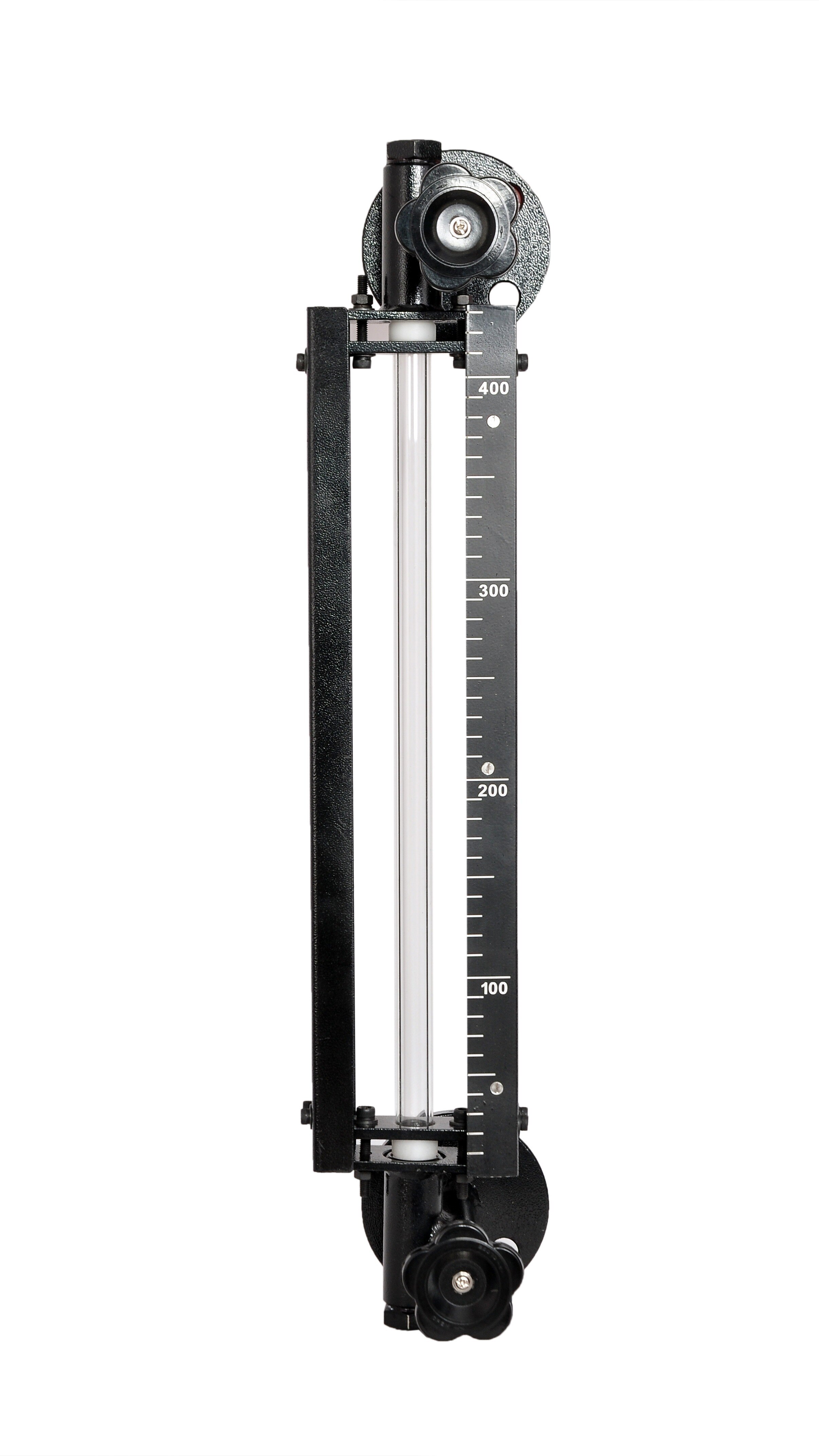
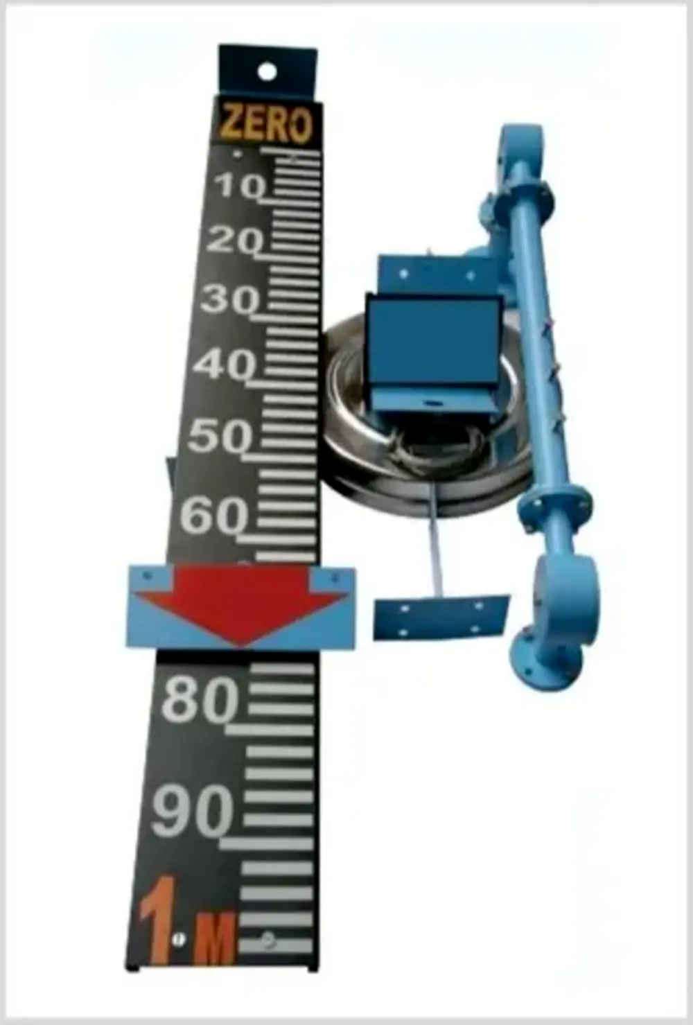 | Level Indicator The Float & Board Level Indicators consists of a float connected to a pointerthrough a rope via a set of pulleys. View product → |