The correct instrument depends on what the level signal must do, the tank geometry, and the liquid and vapour conditions around the sensor. By the end, you will be able to define the measurement range, eliminate incompatible technologies, and specify an instrument that remains useful during filling, emptying, cleaning, and abnormal operation.
Key takeaways
- Choose continuous measurement, point detection, or both before comparing instruments.
- Set the measuring span between tank datum and actual operating limits.
- Check liquid properties, pressure, temperature, vapour, foam, and agitation.
- Specify process connections, materials, output signal, alarms, and calibration access.
Define the level signal before choosing the instrument
When you choose level instrument for tank service, define the required signal before comparing technologies: continuous level measurement, point-level detection, or both.
| Option | What it does | Typical use |
|---|---|---|
| Continuous transmitter | Delivers a changing level value | Display, remote monitoring, inventory, batching, or pump control |
| Point-level switch | Acts at one defined level | Pump start/stop, low-low protection, or high-high alarm |
| Both | Combines measurement with an independent switch action | Process control plus overfill or empty-tank protection |
Do not treat a transmitter’s accuracy specification as proof of overfill protection. Specify the separate high-high alarm or shutdown action, de-energized fail state, response time, proof-test method, diagnostic coverage, hazardous-area requirements, and safety requirements. For a safety instrumented function, define the lifecycle requirements under IEC 61511.
State the required output: 4–20 mA, switch contact, digital protocol, or local indication. For a point-level switch, check switching hysteresis, resistance to coating, and proof-test access. Specify damping, update time, alarm delay, and the maximum acceptable time from a genuine level excursion to action.
A fast reading can feed turbulence into a control loop; excessive damping can delay a genuine high-high trip. The cheapest sensor is unsuitable if it cannot deliver the required action.
Set the usable range from the tank datum to the real operating limits
Set the usable measurement range on a dimensioned tank drawing before comparing technologies. A range that covers the vessel height is inadequate when the instrument cannot measure near its process connection or below the probe’s usable low point.
1. Mark the tank datum or zero reference, minimum operating level, maximum working level, high-high trip level, nozzle elevation, and every region the instrument cannot measure. Show these dimensions vertically.
2. For a top-mounted probe, draw the dead zone or blocking distance below the process connection. Check that the maximum level remains below this zone. Specify the probe length or cable length, required resolution, and level accuracy.
3. Match accuracy to the job. Inventory measurement, batching, process control, and custody transfer have different tolerances. A narrow vertical tank may need finer resolution than a wide horizontal tank holding the same volume.
4. Map the tank geometry and obstructions: horizontal-tank shape, cone bottom, underground installation, small-diameter nozzle, internal coil, ladder, agitator, and stilling well. A cone low point can fall below the usable range, while a side nozzle near an inlet can read turbulence instead of level.
5. For a bypass chamber or stilling well, specify equalization openings, circulation path, isolation valves, and drainability. A plugged opening or closed valve can leave the instrument showing a calm but false level.
Then verify that the selected measurement range covers every required operating point, alarm point, and control action without entering an exclusion zone.
Check the liquid, pressure, temperature, and vapour conditions
Check the liquid, pressure, temperature, and vapour conditions before choosing a level instrument. Match every wetted or exposed material to the actual liquid, not merely the instrument’s trade name.
Record liquid density and its operating range, viscosity, conductivity, corrosiveness, suspended solids, crystallisation, coating tendency, and liquid compatibility with SS 304, SS 316L, PTFE, titanium, seals, and cable insulation. Include the diaphragm, antenna, enclosure, cable entries, and process connection.
- Record normal and upset pressure, vacuum, temperature cycling, washdown, CIP, and SIP conditions.
- For hydrostatic level measurement, state the density used for calibration and every condition that changes it, including concentration, temperature, and phase. A fixed-density calibration creates an approximately proportional level error when density shifts.
- For float and displacer instruments, check density, viscosity, solids, turbulence, guide-tube clearance, and fouling. Buoyancy changes with density.
| Tank condition | Specify | Consequence of a wrong choice |
|---|---|---|
| Open tank | Reference pressure to atmosphere | Vapour pressure can distort the reading |
| Pressurised tank or vacuum tank | Compare bottom pressure with vapour-space pressure | The displayed level can be plausible but false |
| DP installation | Dry leg, wet leg, remote seal, capillary, condensate, and impulse-line arrangement | A blocked, flooded, or incorrectly heated reference leg shifts the reading |
For hygienic service, specify the process connection, seal, surface finish, drainability, and dead-leg limit. Confirm that the arrangement survives cleaning and sterilisation without corrosion, plugging, coating, or seal and cable-insulation damage.
Compare sensor principles against the tank’s failure modes
Choose the principle that survives your tank’s failure modes, not the instrument with the best nominal accuracy.
| Option | Main trade-off | Reject or confirm by checking |
|---|---|---|
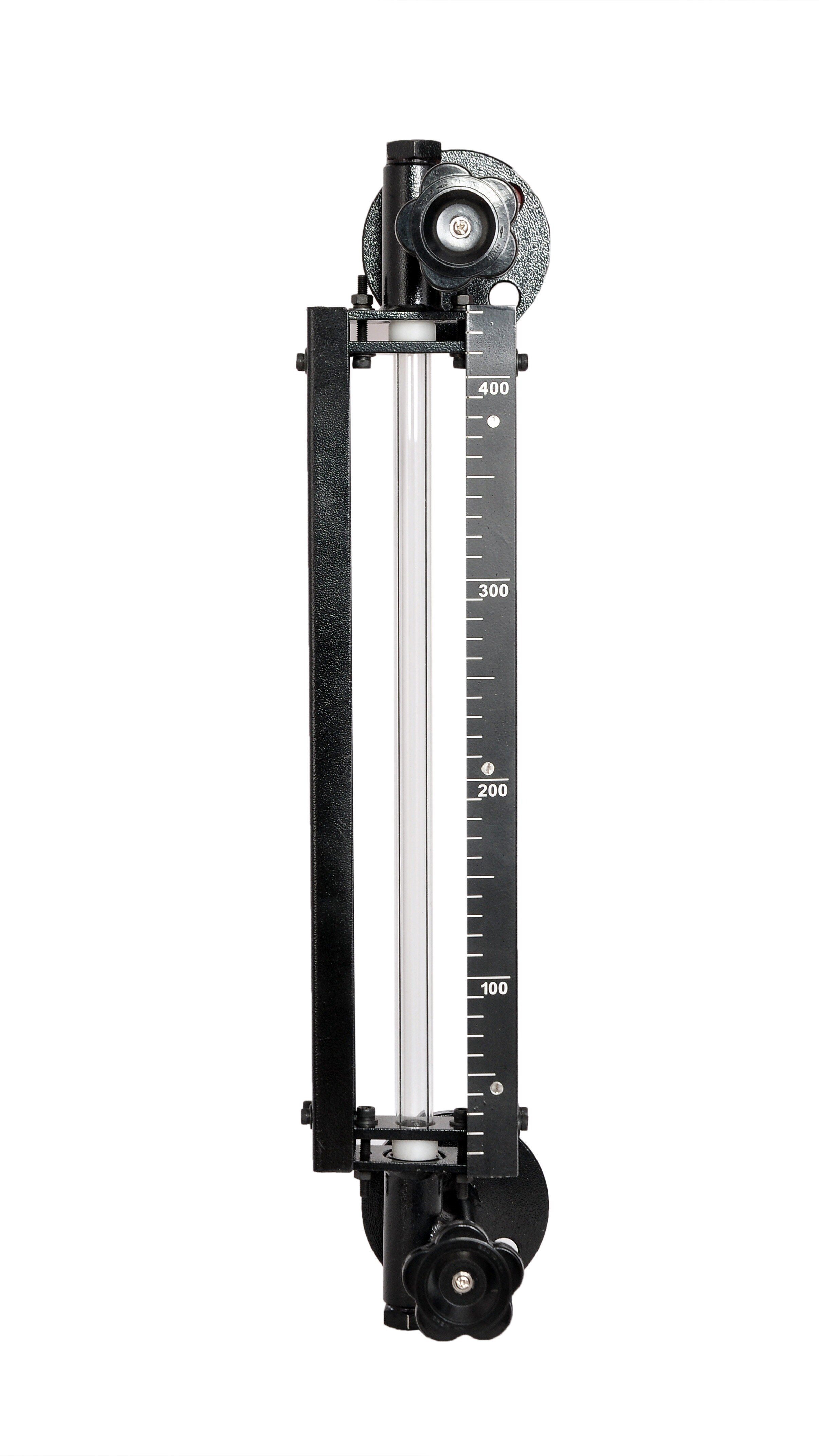
| Float-and-board indicator | Simple, visible, and independent of electrical power; it cannot provide a remote control signal. | Confirm clear mechanical travel, then inspect the rope, pulley, float, and guide for fouling or binding. |
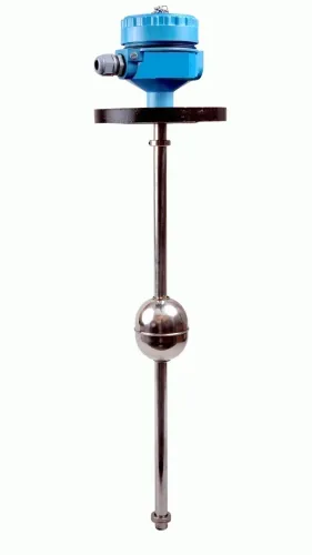
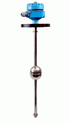
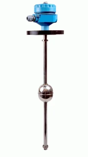
| Float transmitter | A straightforward continuous signal for simple tanks; moving parts add maintenance and can stick. | Confirm controlled turbulence, density, viscosity, solids, and mechanical clearance around the float. |
| Side-mounted switch | Defined high, low, or overfill action with simple wiring; it is not continuous measurement. | Check switching hysteresis, response time, coating resistance, proof-test method, and fail-safe state. |
| Hydrostatic transmitter | No roof target is needed; pressure measurement fails when density or pressure reference changes. | Check density variation, diaphragm damage, impulse-line plugging, and the correct reference pressure. |
| Noncontact radar | Radar level measurement handles vapour, temperature gradients, and changing gas composition better than ultrasonic level measurement. | Provide a clear electromagnetic path; match antenna, frequency, nozzle geometry, dielectric response, and false-echo mapping. |
| Ultrasonic | No wetted probe, but sound is disrupted by foam, condensation, dust, vapour stratification, and turbulence. | Confirm a clear acoustic path and a calm, clean surface. |
| Guided-wave radar | The probe suits confined mounting and some foam; coating, bridging, contact, or poor support can lose the signal. | Verify probe materials, anchoring, clearance, length, and buildup risk. |
| Capacitance probe | Compact and useful with stable product properties; deposits can create false high or low readings. | Confirm stable dielectric behaviour and controlled coating, especially with conductive deposits. |
Treat a point switch as an independent protective action, not as a substitute for a continuous transmitter. A capacitance probe or float transmitter that works in clean service can become the wrong choice after viscosity, coating, or agitation changes.
Turn the selection into an installation and purchase specification
Treat tank level sensor selection as a complete instrument installation specification: mounting often determines performance more than the sensing principle. Locate the nozzle away from inlets, agitator blades, heating coils, roof supports, ladders and heavy condensation.
1. For radar, specify frequency, antenna size, nozzle dimensions, beam clearance, grounding and false-echo suppression together. For ultrasonic, record transducer temperature, vapour conditions and the unobstructed acoustic path.
2. If you use a stilling well or bypass chamber, size its openings for liquid viscosity and the required response time. A plugged equalisation hole or closed isolation valve can leave the instrument showing a calm but unrepresentative level.
3. Put these purchase details on the specification: process connection, wetted materials, enclosure and cable-entry rating, ambient temperature, output, supply voltage, display, calibration access and removal method. State whether the tank must be emptied for service.
4. Define the maximum alarm response time from a real excursion to the alarm or control action, then specify damping, update time and alarm delay. Ask the supplier to review the dimensioned tank drawing, liquid data, pressure and temperature envelope, cleaning cycle and failure response in writing.
Filpro Sensors Pvt Ltd can be included in that review when you compare industrial level measurement, indication, transmission and control options. Judge the recommendation against the documented duty, not a catalogue range alone.
Related products
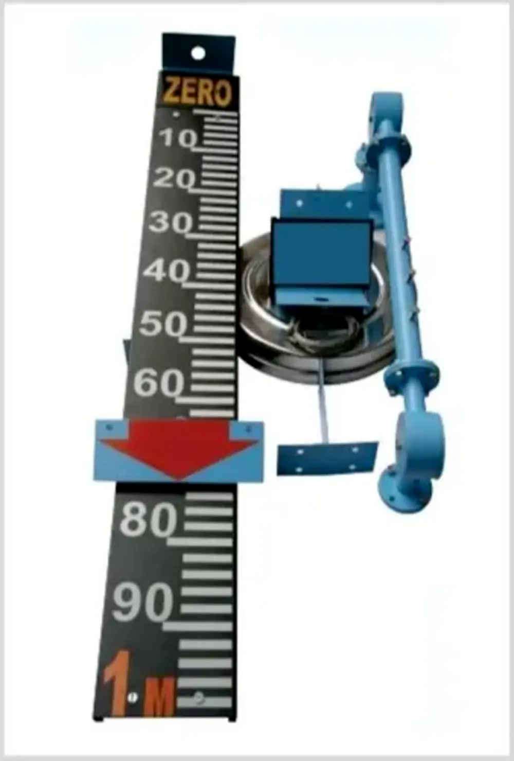 | Level Indicator The Float & Board Level Indicators consists of a float connected to a pointerthrough a rope via a set of pulleys. View product → |
 | Level Transmitter Float Level Transmitters Are Ideal For Continuous Level Monitoring In Water, Diesel, Chemical And Oils For Accurate Level Measurement. View product → |
Frequently asked questions
How do you choose the right level instrument for a tank?
Define the required signal first, set the usable range, check process conditions, compare sensor principles against failure modes, and write the installation specification.
What tank conditions must you check before selecting a level instrument?
Record the liquid, density, conductivity, viscosity, temperature, pressure, vapour, foam, agitation, corrosiveness, and any solids or buildup.
What is the difference between continuous level measurement and point-level detection?
Continuous measurement reports level across a defined range, while point-level detection switches when liquid reaches a fixed high, low, or intermediate point.
What belongs in a tank level instrument purchase specification?
State the measuring range, process connection, wetted materials, temperature and pressure limits, output signal, alarm function, enclosure, mounting position, and calibration requirements.
Related products
 | Level Switch Filpro offers most reliable, cost effective Side Mounted Level Switch for point level sensing. View product → |
 | Level Transmitter Hydrostatic liquid level transducers and transmitters with flush diaphragm is designed fora wide variety of level measurement applications. View product → |
 | Level Sensor Atex approved Float Level Transmitter : Over All Length: 300mm to 5000mm Input: 16V DC to 30V DC Output: 4-20mA / 0-10V DC Resolution: 5mm / 10mm... View product → |
 | Level Transmitter Ultrasonic Level Sensor is a non-contact ultrasonic continuous level measurement product based on sound technology. View product → |