Overflow protection depends on more than placing a float near the top of a tank. You need the correct trip elevation, a circuit that responds safely to faults, and a shutdown or alarm that has been tested as an entire loop.
Key takeaways
- Set the high-high trip below the tank’s overflow elevation.
- Use a shutdown circuit that stops the inlet, not just an alarm.
- Separate automatic fill control from independent high-level protection.
- Test the sensor, wiring, logic, and final shutoff device together.
How the switch turns rising liquid into a shutdown
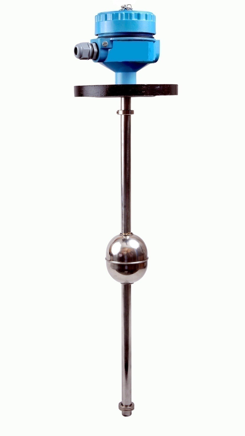
As liquid rises to the high-high setpoint, it moves a float or actuates another sensing mechanism at a defined elevation. The level switch changes an electrical or pneumatic output; that signal then commands the equipment that stops incoming liquid.
- The sensing mechanism detects the setpoint.
- An input module or logic solver receives the switch’s changed state.
- The logic solver starts the configured response, such as stopping the fill pump, closing an inlet valve, or triggering an alarm.
- The final element interrupts inflow, while the operator confirms the alarm and investigates the cause.
The switch alone is not tank overflow level protection. The complete function includes the sensor, signal processing, and final action. A low-level switch serves a different purpose, such as starting a pump, stopping it to prevent dry running, or maintaining a process level.
Set the high-high point below the overflow nozzle, inlet, roof, and vent with enough freeboard for liquid that continues entering after detection. Calculate that margin from inflow rate, switch response, input and logic delays, pump or valve shutdown time, valve leakage, liquid in the filling line, and surge.
A trip point merely below the nozzle is not enough.
Keep any bypassed switch, inhibited shutdown, or unacknowledged alarm visible and controlled through documented authorization and restoration. The final position—valve closed or open—comes from the process hazard analysis. API 2350 offers useful overfill-prevention concepts for petroleum storage facilities, not a universal code for every tank.
How to calculate a safe high-level trip point
Install the high-level switch at the highest liquid elevation that still leaves the tank’s required freeboard. That elevation must sit below the lowest overflow path, vulnerable opening, roof or vent limitation, and the level reached by liquid that continues entering after the trip.
1. Define the maximum safe liquid height from the tank drawing. Mark the overflow nozzle, inlet, vent, roof, internal coils, and any opening through which splashing could escape.
2. Calculate post-trip inflow. Multiply the maximum credible filling rate by the total delay: switch response, input and logic-solver delay, pump stopping delay or inlet-valve closure time, and any liquid already held in the filling line.
3. Convert that volume into height. For a cylindrical tank, divide the post-trip volume by the tank’s liquid surface area. For a horizontal, conical, or irregular tank, use its calibrated volume-to-height chart; surface area changes as the level rises.
4. Add allowances for valve leakage, pump coast-down, liquid momentum, turbulence, foam, and agitation. Set the high-level switch setpoint below the safe maximum by the combined calculated height and these allowances.
Test the actual shutdown time during commissioning, including the final valve’s closing stroke or the pump’s rundown. Do not consume the available freeboard with an unnecessary signal delay. Keep this switch independent from the routine level transmitter, including separate process connections, power, and logic where the risk assessment requires independence.
How high-level protection differs from low-level control
High-high shutdown and a low-level switch solve opposite failures. A low-level switch starts or stops a pump, or prevents dry running, as inventory falls. A high-high shutdown acts when filling continues beyond the normal operating range because the control loop, operator, or filling equipment has failed. The two functions are not interchangeable.
| Protection | Purpose | Typical response |
|---|---|---|
| Low-level switch | Maintains operating inventory or protects a pump from loss of suction | Starts or stops a transfer pump |
| High-high shutdown | Limits overfill after normal control has failed | Stops filling, closes an inlet valve, or raises an alarm |
Use independent protection for the high-high function. A second software alarm from the same transmitter does not provide equivalent independence, because one failed sensor, power supply, cable, logic path, or process connection can remove both layers.
A complete overflow function includes:
- A high-level sensor or switch
- Signal processing or a logic solver
- A final element, such as a pump stop or shutoff valve
The switch alone cannot prevent overflow. If its shutdown is bypassed or its alarm is inhibited, display that condition to operators and require documented authorization, reason, and restoration. An unacknowledged alarm also needs clear visibility during filling.
Keep the high-high shutdown available while the low-level control loop operates normally. The control loop manages inventory and trends level; the shutdown exists for the control loop’s failure.
How to wire the switch for a dependable shutdown
A dependable tank overflow level switch solution normally uses a relay or contactor rather than interrupting the motor directly. A float switch contact is not usually rated for motor-starting current, and switching that load can weld the contacts or create arcing.
Use the switch to control a relay coil; let the relay or motor contactor handle the pump circuit.
1. Define the safe final action from the process hazard analysis. Closing an inlet valve suits an incoming liquid hazard, while another process may require a valve to remain open to prevent overpressure. “Fail-safe shutdown” does not mean the same valve position in every installation.
2. Prefer a de-energize-to-trip arrangement. During healthy operation, the switch circuit and relay coil remain energized; a high-high signal, broken wire, or loss of control power drops the relay and stops the pump or commands the valve.
3. Use a normally closed level switch in the trip circuit when opening the contact must initiate shutdown. A normally open level switch closes at high level, but a broken wire or lost power can leave the motor running unless separate diagnostics detect it.
4. Keep the high-high switch independent of routine control. Do not share its transmitter, power supply, logic input, process connection, or impulse line when that shared component could defeat both layers.
5. Test the complete chain: switch movement, relay action, contactor release, valve travel, alarm, and restart interlock. Filpro Sensors Pvt Ltd can be asked to confirm contact ratings, mounting orientation, liquid compatibility, and reset behaviour before selection.
A normally closed circuit still needs proof testing because a switch stuck closed will not reveal its own mechanical failure. Calculate the shutdown response as a complete function, not as a switch rating alone.
Related products
 | Level Switch Filpro offers most reliable, cost effective Side Mounted Level Switch for point level sensing. View product → |
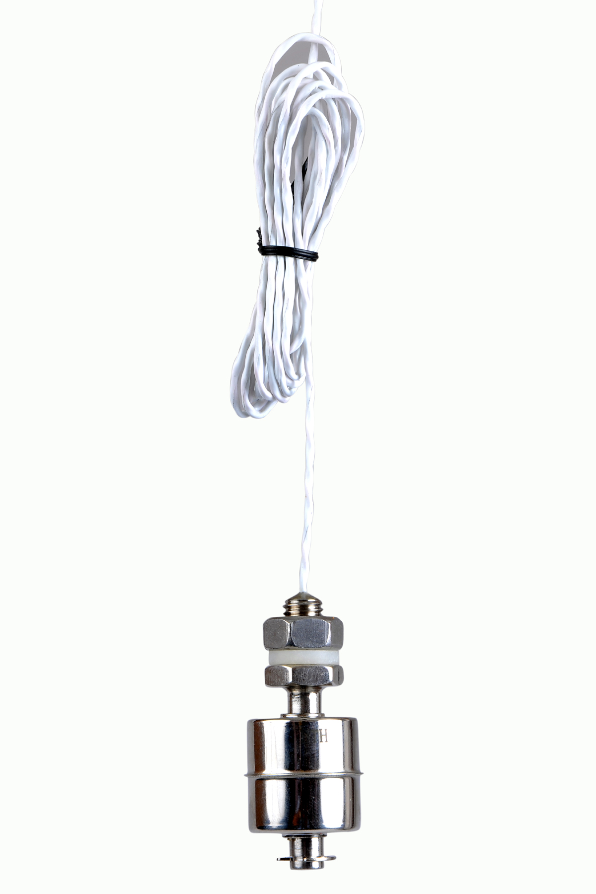 | Level Switch Stainless steel level switch - Miniature Stainless steel Miniature Level Switch is a compact construction, suitable for mounting vertically. View product → |
How to test the complete overflow protection loop
Test the loop from the tank-side sensing element to the final action, not from a control-system cabinet terminal. A cabinet simulation proves the input card received a signal; it does not prove that an installed float moves freely, a probe is not coated, or a shutdown valve closes.
1. Place the filling system in a controlled test state. Stop normal transfers, notify affected operators, and prevent a test trip from creating a hazardous restart or unexpected discharge.
2. Actuate the installed sensing element at its high-high position using the manufacturer’s test lever, test magnet, calibrated lift, or another approved method. Do not rely on a simulated signal injected at the input card.
3. Confirm the signal travels through the actual wiring and input card to the logic solver. Record the high-high alarm, panel indication, remote notification, and alarm timestamp.
4. Acknowledge the high-high alarm, then verify the acknowledgement status is visible. Confirm that any bypass or inhibited shutdown is alarmed, authorised, recorded, and removed after testing.
5. Observe the final shutdown device: confirm the fill pump stops or the inlet valve reaches its required safe position. Check the position indication, and verify that the valve does not reopen until the defined reset procedure is completed.
6. Restore the system, clear the alarm, and document the actuation method, response times, final position, defects, and restoration authorisation.
An overflow protection inspection should also check for coating, corrosion, loose terminals, damaged cables, and an obstructed float. Repeat the proof test after repairs or changes to the switch, logic, wiring, pump, or valve.
Frequently asked questions
How does a level switch stop a tank from overflowing?
At the high-high level, the switch changes an electrical or pneumatic output. A relay, safety controller, or control system then stops the inlet pump or closes the fill valve.
How do you calculate a safe high-level trip point?
Place the trip below the overflow elevation by allowing for switch accuracy, liquid rise during shutdown, inlet flow, valve or pump stopping time, and the tank’s usable freeboard.
What is the difference between high-level protection and low-level control?
Low-level control maintains inventory by starting or stopping equipment during normal operation. High-level protection is an independent shutdown that acts before the tank overflows.
How should you wire a level switch for dependable shutdown?
Use a de-energize-to-trip circuit where loss of power, a broken wire, or a failed relay produces a safe shutdown. Route the output through the equipment that stops incoming flow.
How do you test a tank overflow protection loop?
Raise or simulate the switch signal, verify the input at the control panel, confirm the shutdown logic, observe the pump stop or valve close, and restore the system only after checking the alarm and reset.
Related products
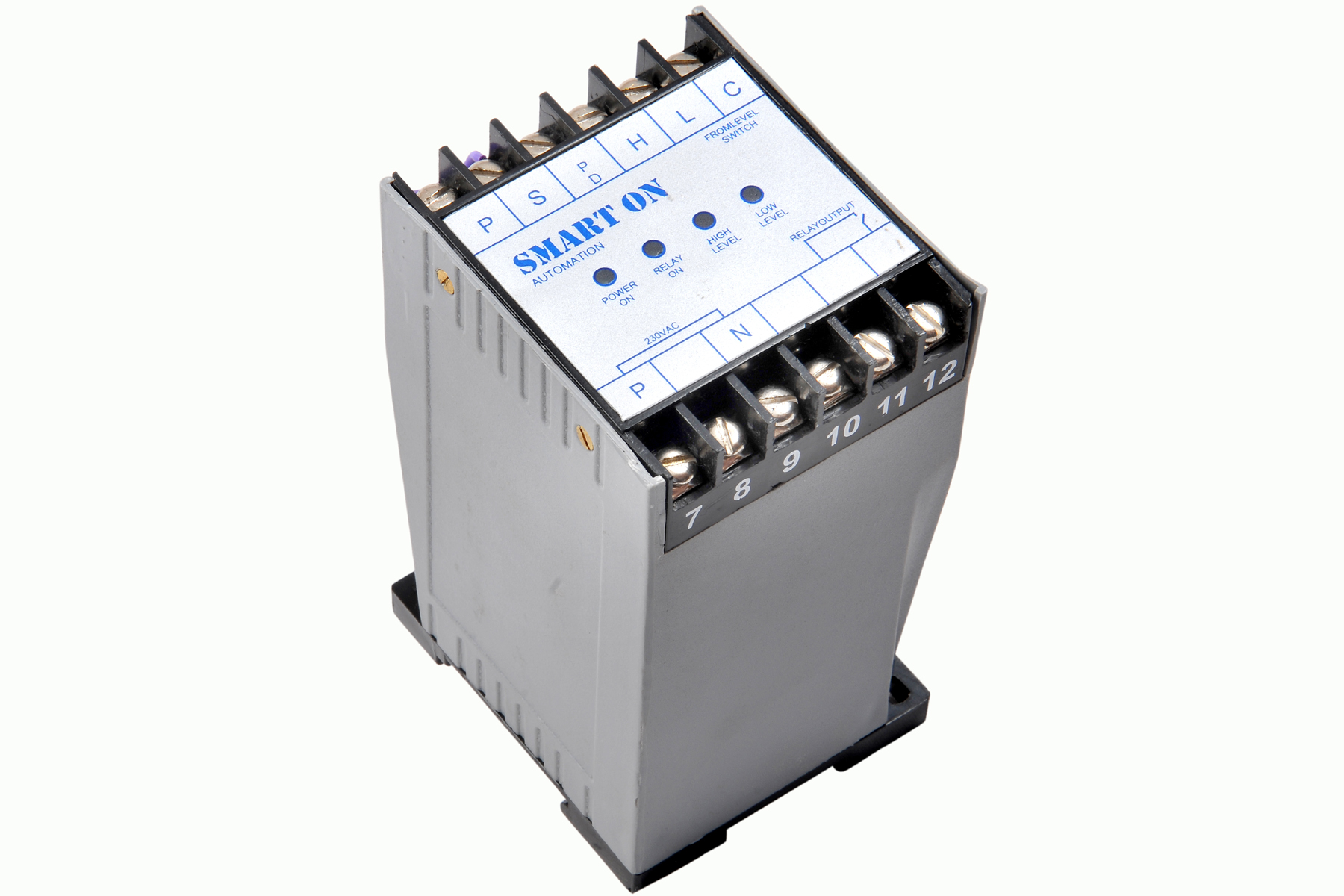 | Controller Filpro Sensors Pvt Ltd manufactures industrial Level Controller (Smart On) to automatically start & stop the pump. View product → |
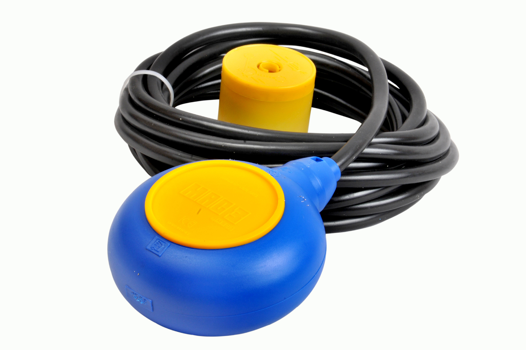 | Level Switch Cable Float Switch is mainly used for the automatic working of small pumps and cellar emptying pumps in liquids a little bit agitated. View product → |
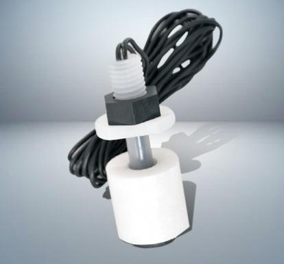 | Level Switch Plastic Miniature Level Switch is available in PP construction with PP Float Switching Voltage: 24V DC Switching current: 0.1A Mounting thread size:... View product → |
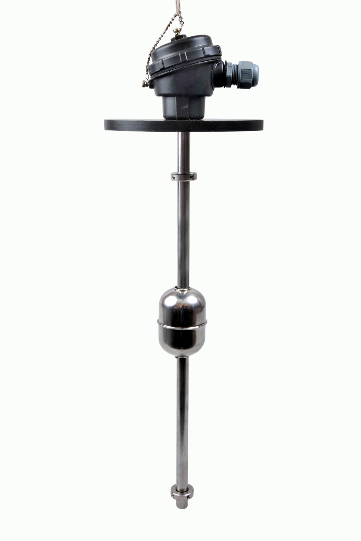 | Level Switch The Magnetic Level Switch consists of the non-abrasive float carrying permanent magnet and non-ferrous stem carrying one. View product → |