A tank level reading is only useful when you know how the instrument turns a physical surface, pressure, or probe position into a value your control system can use. By the end, you will be able to distinguish sensor types, check whether a selected range and installation will work, and commission the complete measurement loop without confusing tank height with usable measurement range.
Key takeaways
- Continuous sensors output changing level values across the tank’s operating range.
- Choose sensing technology based on liquid properties, tank geometry and operating conditions.
- Match sensor range to usable tank height, not the vessel’s total height.
- Commission the complete loop from sensor installation through PLC or SCADA display.
What makes level measurement continuous
A continuous liquid level sensor produces a changing level value across the tank’s operating range, rather than switching only when liquid reaches a fixed point. The sensing element detects the physical condition; a continuous liquid level transmitter converts that measurement into a signal for a PLC, SCADA system, display or alarm logic.
| Type | What it reports | Typical output or action |
|---|---|---|
| Continuous liquid level sensor | Liquid position at any point within its effective range | Changing measurement from a float, radar, ultrasonic, capacitance or pressure element |
| Point-level switch | Whether liquid has reached a setpoint such as low, high or overfill | On/off contact or switching signal |
| Transmitter | A sensor measurement formatted for remote equipment | 4–20 mA, voltage, pulse or digital signal |
A hydrostatic transmitter infers level from liquid head, approximately ΔP = ρgh. Density changes from composition or temperature can therefore change the indicated level; a water calibration can misread another liquid. In a closed tank, a differential-pressure transmitter also compensates for vapor-space pressure through its low-side connection.
Check the effective range, not just tank height. Radar and ultrasonic devices have near-field dead zones, while pressure devices depend on calibrated span and mounting elevation. Damping steadies the output but delays changes, and 4–20 mA values map configured range points to 4 and 20 mA, not necessarily the tank’s physical bottom and top.
How the main sensing principles find the liquid surface
Each principle converts a different physical clue into level: a float’s position, a sound or microwave echo, pressure at the tank bottom, or electrical capacitance. The best continuous liquid level measurement device matches that clue to the liquid, tank and installation.
| Principle | How it finds the surface | Where it fails |
|---|---|---|
| Float and magnetic | A float follows the surface; magnetic coupling or magnetostrictive timing reports its position along a stem. | Wrong float density, sludge, wax, solids, a damaged float or restricted movement gives a false level. |
| Ultrasonic | The transmitter measures the time for a sound pulse to travel to the surface and return. | Foam, vapour, turbulence, condensation, temperature changes and internal obstructions weaken or distort the echo. |
| Hydrostatic | Pressure at the lower connection follows height: pressure = density × gravity × height. | Changing density changes the reading. In a closed tank, uncorrected vapour pressure also makes level appear to change. |
| Capacitance | The probe and tank wall form a capacitor; the immersed length changes capacitance as liquid replaces air. | Coating on the probe, a changing dielectric constant, or poor grounding shifts the calibration. |
| Guided-wave radar | A microwave pulse travels down a probe and reflects from the surface. | Buildup, bridging, mechanical damage and probe-installation limits interrupt the signal. |
| Free-space radar | It calculates antenna-to-surface distance from microwave travel time. | Low reflectivity, a low dielectric constant, false echoes, obstructions and poor antenna aiming create errors. |
Keep the surface inside the effective range: radar and ultrasonic instruments have near-field dead zones, while pressure instruments have calibrated spans tied to mounting elevation.
How the reading travels from the tank to the control room
A sensing element changes with liquid level, and transmitter electronics convert that change into an engineering value. A continuous liquid level transmitter then sends the value to a PLC, SCADA system or local display.
The configured lower and upper range points usually become 4 mA and 20 mA; 4 mA does not necessarily mean an empty tank, and 20 mA does not necessarily mean the tank roof. Verify output range, alarm behavior and display scaling during commissioning.
- 4–20 mA: the PLC’s analog input converts loop current into level using its configured scaling.
- Voltage: a 0–10 V or similar signal represents the configured range, but cable length and electrical noise can affect it.
- Pulse: pulse frequency or width represents level or distance, requiring a compatible counter or pulse input.
- Digital: HART, Modbus or another protocol carries the value, diagnostics and configuration data.
Damping and digital filtering steady a noisy reading but delay it. A long setting can hide a rapid fill or make an overfill alarm and control loop respond late. In a closed tank, hydrostatic measurement must subtract vapor-space pressure; otherwise pressurising the vessel can appear as a level increase.
Density changes also affect ΔP = ρgh, so a water calibration can misread another liquid. Keep actual levels outside radar or ultrasonic dead zones and within the calibrated span; a magnetostrictive float must also move freely and suit the liquid.
How tank geometry, range and installation change the result
Select probe length and measuring range from the actual operating levels, not the tank shell height. Keep the highest and lowest liquid levels inside the transmitter’s effective span, leaving the manufacturer’s dead zone clear near a radar or ultrasonic sensor and any inactive section at a probe’s end.
A 4–20 mA continuous liquid level transmitter maps configured lower and upper range values to 4 mA and 20 mA; these points do not have to equal the tank’s physical bottom and top. Set the reference elevation explicitly, then verify display scaling, damping and alarm limits during commissioning.
- Horizontal tank: Mount the sensor where liquid reaches it across the required working volume. A high side location can leave usable liquid below the sensing point; a low side location can expose the instrument to sediment or nozzle interference.
- Cone-bottom tank: Define whether “zero” means the cone tip, the outlet elevation or the transmitter’s reference point. A short probe or poorly placed pressure connection can miss the final drainable volume.
- Obstructed tank: Keep radar or ultrasonic beams away from ladders, coils and stiffeners. Relocate the instrument or configure false-echo suppression when an obstruction creates a stronger reflection than the liquid surface.
For a closed tank, use differential pressure with the high-side connection on the liquid and the low-side connection in the vapor space. A gauge-pressure device can report a changing level when vessel pressure changes.
The installed accuracy of any continuous liquid level sensor also depends on mounting, density, calibration and signal faults, not its datasheet accuracy alone.
How to choose and commission a reliable tank-level loop
Choose a continuous liquid level measurement device by comparing process conditions and failure consequences, not headline accuracy. Record liquid density range, dielectric constant, conductivity, temperature, pressure, vapour, foam, agitation, coating, tank material, nozzle location, obstructions and required response time.
Filpro Sensors Pvt Ltd belongs on the shortlist only after these details match the selected principle and effective range.
| Measurement principle | Compare before selecting | Investigate before approval |
|---|---|---|
| Hydrostatic | Density, mounting elevation and tank pressure | Use vapor-space compensation in a closed tank; gauge pressure alone shifts with vessel pressure |
| Radar | Surface reflectivity, dielectric constant, antenna position and false echoes | Check internal obstructions and the near-field dead zone |
| Ultrasonic | Vapour, temperature, foam, turbulence and acoustic obstruction | Confirm the empty level stays outside the blocking zone |
| Capacitance | Liquid dielectric properties, probe coating and tank grounding | Recalibrate after composition changes or coating |
Commission the continuous liquid level transmitter with a signed test record:
- Confirm the configured lower and upper range values map to 4 mA and 20 mA; do not assume they represent the tank’s physical bottom and top.
- Check output limits, fault alarms, damping, engineering units and display scaling separately.
- Inject 4, 12 and 20 mA at the transmitter or loop and verify the PLC, SCADA value and alarm states.
- For differential pressure, verify high side to liquid, low side to vapour, impulse-line condition and reference elevation.
- Compare readings at low, middle and high levels against a sight gauge, dip measurement or calibrated independent gauge. Investigate any repeatable offset before accepting the loop.
Related products
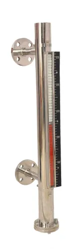
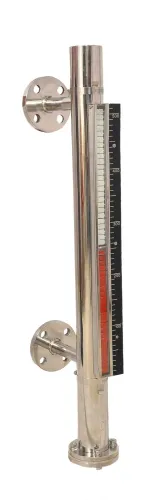
 | Level Transmitter Float Level Transmitters Are Ideal For Continuous Level Monitoring In Water, Diesel, Chemical And Oils For Accurate Level Measurement. View product → |
 | Level Transmitter Ultrasonic Level Sensor is a non-contact ultrasonic continuous level measurement product based on sound technology. View product → |
Frequently asked questions
What makes liquid level measurement continuous?
A continuous liquid level sensor produces a changing level value across the tank’s operating range instead of switching at fixed points.
How do continuous level sensors find the liquid surface?
Different sensors detect the surface through principles such as hydrostatic pressure, float position, ultrasonic echo, radar reflection or guided-wave radar.
How does a tank-level reading reach the control room?
A transmitter converts the sensing result into a signal, such as 4–20 mA or a digital protocol, for a PLC, SCADA system, display or alarm logic.
What affects continuous tank-level measurement accuracy?
Tank geometry, measurement range, mounting position, turbulence, vapour, foam, temperature, density and installation quality all affect the result.
Related products
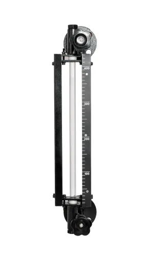
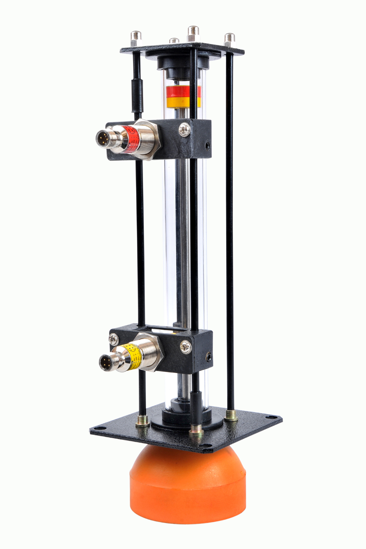 | Level Gauge Oil Level Indicator is designed to indicate the coolant and hydraulic oil level inside the tank with a visual indicator above the tank. View product → |
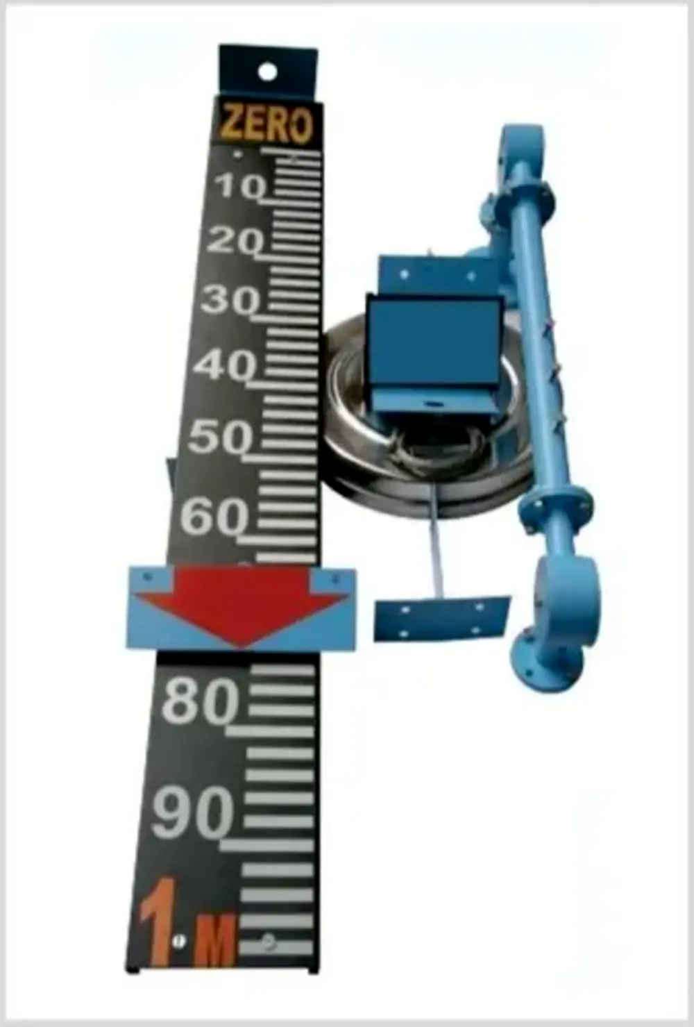 | Level Indicator The Float & Board Level Indicators consists of a float connected to a pointerthrough a rope via a set of pulleys. View product → |
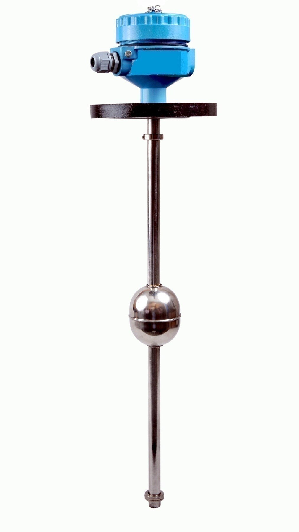
 | Level Sensor Atex approved Float Level Transmitter : Over All Length: 300mm to 5000mm Input: 16V DC to 30V DC Output: 4-20mA / 0-10V DC Resolution: 5mm / 10mm... View product → |
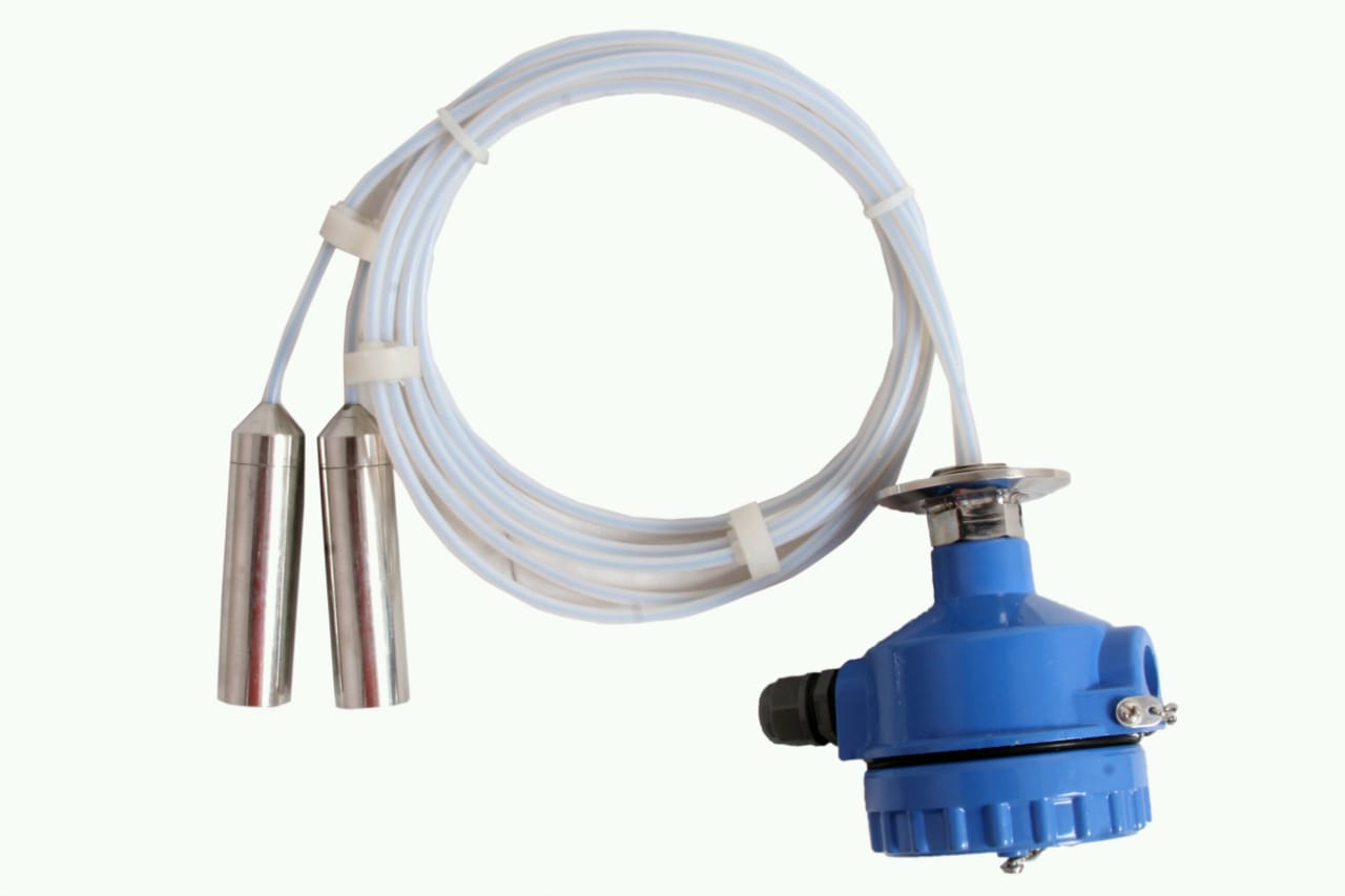 | Level Transmitter can be used for conductive as well as non conductive liquids. View product → |