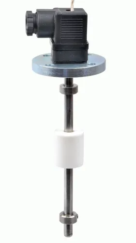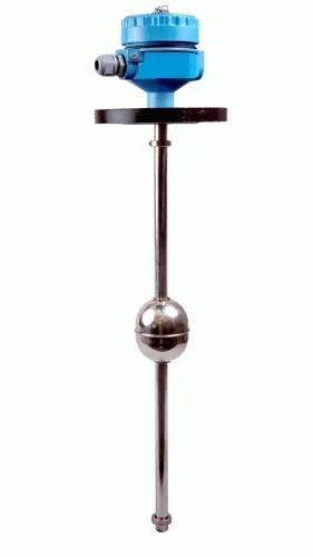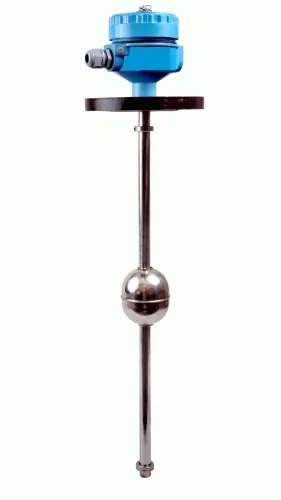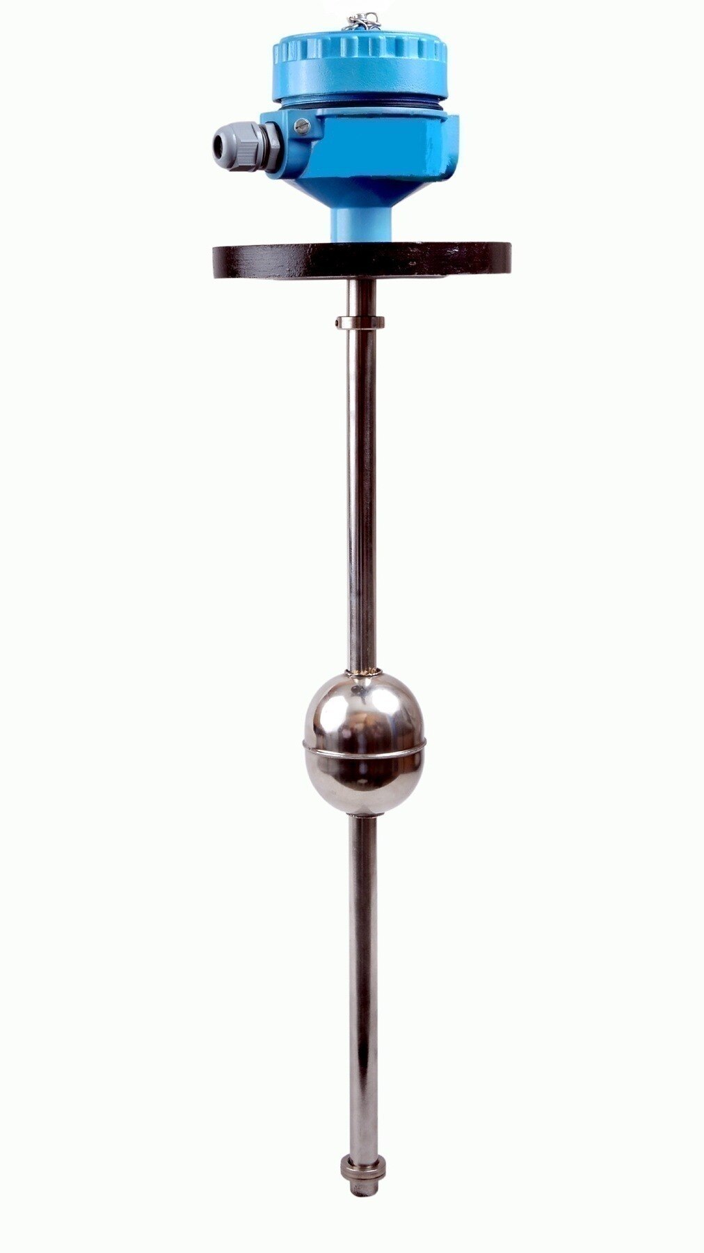
A float responds to buoyancy and mechanical movement, not to liquid height as an abstract value. By examining density, surface condition, deposits, turbulence, installation geometry and vessel shape, you can identify when a reading represents the actual surface—and when it represents the float becoming stuck, submerged or displaced.
Key takeaways
- Check liquid density before trusting a float sensor calibration.
- Do not use a float to detect a hidden interface beneath foam or sludge.
- Clear deposits and account for viscosity, turbulence and restricted movement.
- Confirm tank geometry supports the float’s travel and installation method.
Buoyancy makes density part of the measurement
A float actually measures the liquid’s buoyant force, not its level directly. At equilibrium, the liquid displaced by the float must weigh enough to support it; if density falls below the float’s calibrated range, it rises or sinks at a different height, and a liquid lighter than the float can leave it fully submerged.
A water calibration does not transfer safely to solvents, oils, or concentrated process liquids. This is among the most important float level sensor limitations.
Density changes create three distinct errors:
- The same tank volume can produce a different indication after a density change. The float’s switch point shifts even though the liquid surface has not moved.
- Entrained gas, bubbles, or aeration reduce the effective density around the float. Recirculation, sparging, pumping, and gas-producing reactions can make it rise above its expected position.
- In a liquid-liquid system, similar-density phases, emulsions, or a float density between the two phases prevent reliable interface detection. The float can settle somewhere in the transition zone rather than at a repeatable boundary.
A float indication is not automatically volume, mass, or usable capacity. Convert level to volume with the vessel’s geometry table; convert it to mass only with dependable density and temperature data. A linear conversion fails in horizontal or dished tanks and around internal obstructions.
Sludge, fibres, precipitates, and deposits add another error: the float can stick or become buried, reporting its immobilised position instead of the liquid surface.
Foam, sludge and multiple liquid layers can hide the true surface
A float cannot reliably identify the actual liquid surface when material separates it from the surface or when another liquid forms a second boundary. It reports the position where it rests, rises, or becomes stuck, which can differ from the surface you need.
- Stable foam can support the float, wet it intermittently, or leave it suspended below the liquid. The result is a false high, false low, or rapidly changing reading.
- Debris, fibrous solids, and precipitates can obstruct a guided float. The indication then reflects the point where the float is physically immobilised.
- Sludge can bury the float or pack around its guide, preventing free movement and leaving the sensor fixed while the real level changes.
- Entrained gas and bubbles can lift the float above its expected position. Recirculation, sparging, pumping, and gas-producing reactions make this error difficult to predict.
- An immiscible liquid pair may have an emulsified interface or a broad transition zone. The float can settle inside that zone instead of identifying a repeatable boundary.
A float switch also cannot reveal what happens between its actuation points. It will not show a second surface, stratification, or the rate of level change.
Turbulence and liquid entering near the sensor can repeatedly cross the switch point, causing contact chatter and nuisance alarms; a stilling well, damping, hysteresis, or control delay addresses the movement, not an unmeasurable interface.
Deposits, viscosity and turbulence disrupt float movement
Deposits and viscous liquids can make a float stick, drag, tilt or respond long after the liquid has moved. Coatings add weight and alter the float’s submerged shape; a thick layer can also bind it against a guide tube, stem, chamber wall or switch mechanism. These are core float level sensor limitations.
The risk is highest when the liquid leaves a hard or tacky film. Watch for:
- Crystallising solutions that form bridges between the float and guide
- Waxes, polymers or resins that coat the float and restrict travel
- Suspended solids that collect on the guide, pivot or magnetic coupling
High viscosity does not remove buoyancy, but it increases resistance to movement. The float can lag behind a fast level change, remain at its former position, or return slowly after an excursion. That delay creates hysteresis: the switch changes state at a different level while rising than while falling.
Turbulence produces a different failure. Agitators, waves or an inlet aimed at the float can drive it above and below one switch point repeatedly. The result is contact chatter, nuisance alarms and accelerated relay wear. A stilling well, damping, switch hysteresis or control logic that ignores brief transitions can reduce the problem.
A contaminated guide, bent stem or corroded fitting can also tilt the float and increase friction until it hangs up. If the liquid level then falls, the float may sink with a sudden release rather than track the change, turning a gradual process change into a late alarm.
Tank geometry determines both installation and what level means
Tank geometry determines both where a float can travel and what its indication means. A float reading is a height at one location, not automatically a volume or usable-capacity measurement.
Converting height to volume requires the vessel’s geometry table; a straight linear conversion fails in horizontal, dished, conical, or irregular tanks because cross-sectional area changes with height.
Internal equipment can block or distort that measurement. Check for:
- Heating coils, agitator shafts, baffles, dip pipes, ladders and support brackets in the float’s travel path
- A guide tube or stem that is too short, bent, off-vertical or installed without clearance
- Nozzles, reducers, weld projections or tank roofs that restrict the float before it reaches the intended high or low point
- A float buried or physically immobilised by material entering the guide path
When travel stops early, the sensor reports the float’s last position rather than the actual surface. A high-level switch can therefore remain open after the liquid has risen above its blocked float, while a low-level switch can reset late.
A single float also cannot describe volume accurately across a vessel whose shape changes. In a dished bottom, a small height change may represent little liquid; higher in the same tank, it may represent far more.
Use a calibrated level-to-volume table, and verify that the table matches the tank’s internal dimensions, fittings and usable dead space.
Use a float only after checking the failure conditions
Use a float only after completing process and installation checks, because its switch point, indication and control response depend on conditions beyond tank volume. These checks expose the main float level sensor limitations before you commit to a design.
1. Record the liquid’s minimum and maximum density, operating temperature, viscosity and expected temperature range. Compare these values with the float’s calibrated specific-gravity range, then verify the complete assembly at process temperature.
2. Define the required function. A float can suit a high-level switch or local indication, but deadband, hysteresis, travel and reset time make it a poor choice when a closed-loop controller needs a shorter response period.
3. Check the process for suspended solids, fibres, crystallising material and precipitates. Reject a guided float if material can enter the guide, bury the float or prevent free movement; the reading may then show the obstruction height instead of the liquid surface.
4. Inspect the mounting location for a straight guide, adequate clearance, corrosion resistance and access for cleaning. Keep the float away from internal supports, coils, ladders and inlet streams that can tilt or strike it.
5. Quantify agitation and level-change rate. If the float will repeatedly cross the switch point, specify a stilling well, damping, deliberate hysteresis or control logic that prevents contact chatter.
When comparing a float transmitter from Filpro Sensors Pvt Ltd, request the float material, guide dimensions, switching deadband, calibration range and temperature limits—not only the output signal. Reject the selection if those figures do not cover the actual service.
Related products
 | Level Transmitter Float Level Transmitters Are Ideal For Continuous Level Monitoring In Water, Diesel, Chemical And Oils For Accurate Level Measurement. View product → |
 | Level Sensor Atex approved Float Level Transmitter : Over All Length: 300mm to 5000mm Input: 16V DC to 30V DC Output: 4-20mA / 0-10V DC Resolution: 5mm / 10mm... View product → |
Frequently asked questions
Why does liquid density affect a float level sensor?
A float responds to buoyant force, so a density change alters the height at which it is supported. A liquid lighter than the float can leave it fully submerged.
Can a float level sensor measure through foam or sludge?
No. Foam, sludge and multiple liquid layers can hide the true liquid surface or support the float at the wrong interface.
How do deposits, viscosity and turbulence affect float movement?
Deposits can add weight or jam the float, while viscous liquid slows movement. Turbulence causes the float to bounce instead of settling at a stable level.
Why does tank geometry matter for float level measurement?
The tank shape, internal obstructions, nozzles and guide arrangement determine whether the float can travel freely and what measured height represents.
Related products
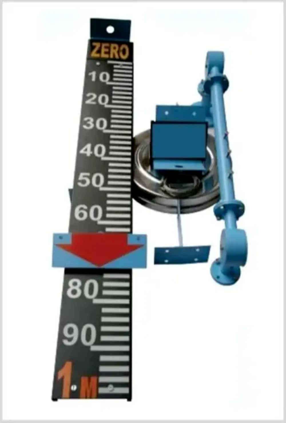 | Level Indicator The Float & Board Level Indicators consists of a float connected to a pointerthrough a rope via a set of pulleys. View product → |
 | Level Transmitter Ultrasonic Level Sensor is a non-contact ultrasonic continuous level measurement product based on sound technology. View product → |
 | Level Switch Filpro offers most reliable, cost effective Side Mounted Level Switch for point level sensing. View product → |
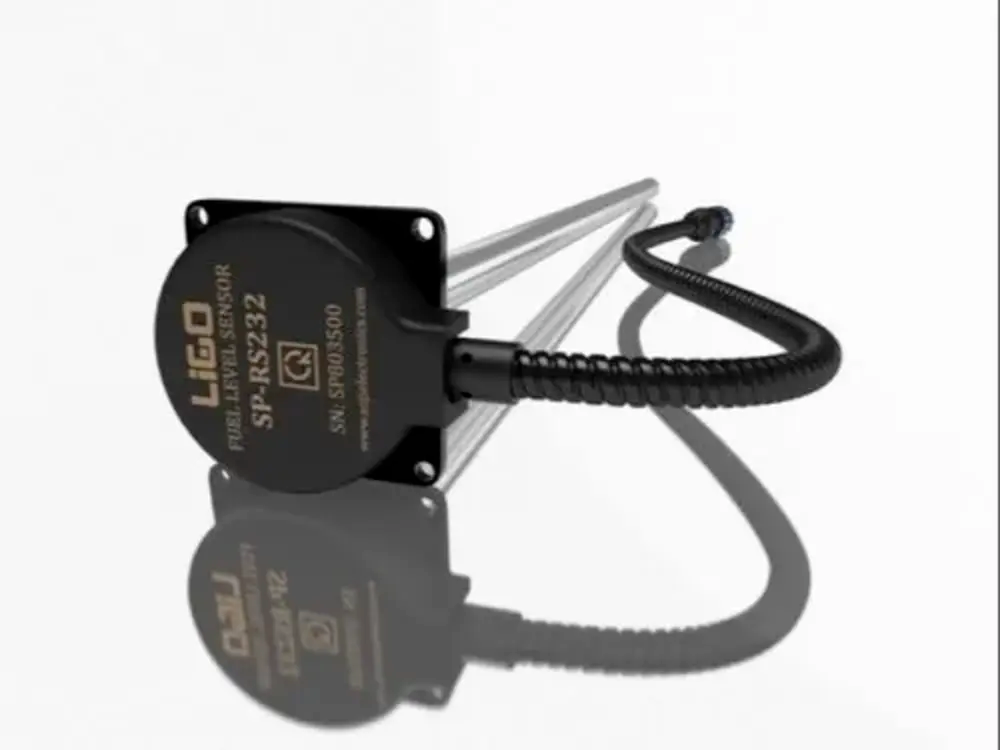 | Level Sensor Ligo fuel sensor for monitoring Diesel and Petrol level in vehicle fuel tanks and DG sets. View product → |