An overflowing tank can continue receiving liquid after an alarm sounds, especially when nobody is available to respond or a pump and valve take time to stop. You will be able to choose the trip point, wire the shutdown path, account for liquid and installation conditions, and verify that the complete protection system works.
Key takeaways
- Use a rising-level contact to stop the pump or close the inlet valve.
- Wire the shutdown circuit to produce a safe response during power or signal loss.
- Match the switch to liquid properties and mount it below the true overflow point.
- Use independent high-high protection when one switch cannot control the hazard.
How the switch turns a rising level into corrective action
A level switch for overflow protection stops filling by changing an electrical contact when liquid reaches a preset elevation. A float rises, or another sensing element detects the liquid, and a relay, contactor, PLC, or pump controller stops the transfer pump or closes the inlet valve.
A switch wired only to a horn creates an overflow alarm; it warns someone but does not remove inflow.
Use an independent high-high level switch alongside the normal level transmitter and control loop. Shared impulse lines, power supplies, I/O cards, or software paths can create one failure instead of two protective layers. Set the trip below the tank rim, leaving freeboard for incoming liquid, switch response, logic delay, valve closing, and pump coast-down.
Nozzle length, vessel tilt, dead volume, and internal obstructions can shift the actual switching elevation.
Wire the trip circuit in this order:
- Select normally closed or normally open contacts according to the required failure response; energized-to-run logic makes loss of power or a broken circuit stop filling.
- Use an interposing relay or suitably rated contactor, and keep the switch circuit isolated from motor current.
- Connect the trip to the pump controller or inlet-valve interlock, not only to the alarm circuit.
- Configure manual reset after a trip so power restoration cannot restart filling automatically.
- Record the as-installed elevation, normal and alarm contact states, annunciation, shutdown action, reset behavior, and bypass status.
Control any bypass with authorization, a time limit, and compensating operating measures. For flammable atmospheres, match the approval to the classified area, gas or dust group, temperature class, protection concept, and installation method; IP65 or IP67 alone is not explosion protection.
A SIL marking on the switch does not rate the complete IEC 61511 protection loop.
How to wire the shutdown circuit for a safe response
Wire the shutdown circuit so a high-level trip removes energy from the final control element, rather than merely sounding an alarm.
1. Set the switch below the tank rim, leaving freeboard for inflow, switch response, logic processing, pump coast-down, and inlet-valve closing time. Record this as-installed trip elevation.
2. Use a normally closed level switch in a monitored input loop when the safe state is an open circuit. During normal operation, the loop energizes a safety relay; a high-level trip, broken cable, lost instrument power, or failed input circuit de-energizes that relay.
3. Apply de-energize-to-trip logic through the complete path: level switch, input diagnostics, relay contacts, contactor or solenoid, and final device. A normally closed contact alone does not make the system fail-safe.
4. Use the relay or PLC output to drop the pump contactor for pump shutdown, or de-energize a valve solenoid that drives the inlet valve closed. Confirm that the valve’s power-loss position is actually closed; a valve that stays open defeats the trip.
5. Do not connect a pump motor or solenoid directly to the level-switch contacts unless their inductive-load rating matches the application. Size the interposing relay, contactor, fuses, and surge suppressor for the manufacturer’s AC or DC utilization category.
6. Define reset behavior before commissioning. A manual reset prevents automatic refilling after power returns; automatic restart requires a documented risk review and a level check.
Test the switch at its actual trip elevation and trace the command through the relay, contactor or valve. Continuity at the switch terminals cannot reveal a seized float, incorrect logic, or stuck shutdown valve.
How liquid properties and mounting location affect reliability
Liquid properties and mounting location affect both whether a switch reacts reliably and the elevation at which it actually trips. A float level switch or displacer depends on buoyancy, so a setpoint proven with water can shift in oil, chemicals, or any liquid with materially different density.
Temperature can change density and viscosity; include the full operating temperature range in the selection.
Foam, entrained gas, waves, heavy turbulence, and coating can cause nuisance trips or prevent a clean trip. Solids can foul a float, restrict movement, or build a bridge around the sensing element.
Keep the device away from inlet jets and agitators, and use a stilling well or protective cage when it will not obstruct solids or cleaning.
A pressure-based switch responds to hydrostatic pressure, which depends on specific gravity, tank pressure, and installation elevation. In a pressurised vessel, confirm the pressure reference as well as the liquid density; otherwise the calculated trip height will be wrong.
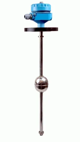
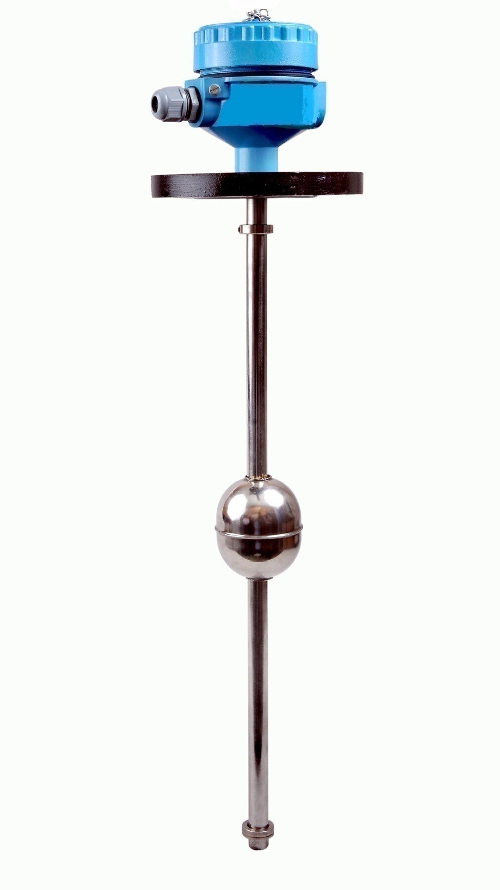
A top-mounted level switch needs its stem, float travel, nozzle length, and internal obstructions checked against the required elevation. A side-mounted level switch can trip at the nozzle centreline rather than the elevation assumed on the drawing, especially when the vessel is tilted or the nozzle contains dead volume.
Before approving a level switch for overflow protection, verify:
- The actual switching elevation and the freeboard needed for inflow, response delay, valve closing, and pump stopping.
- Orientation, vessel tilt, nozzle length, and interference from coils, baffles, or agitators.
- The liquid’s density, solids content, foam, temperature, viscosity, and pressure range.
- Hazardous-area approval where applicable; IP65 or IP67 alone is not explosion protection.
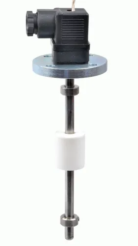
Filpro Sensors Pvt Ltd can use these application details to distinguish when a compact vertical float arrangement is suitable from when a protected or differently mounted switch is safer.
Related products
 | Level Switch Filpro offers most reliable, cost effective Side Mounted Level Switch for point level sensing. View product → |
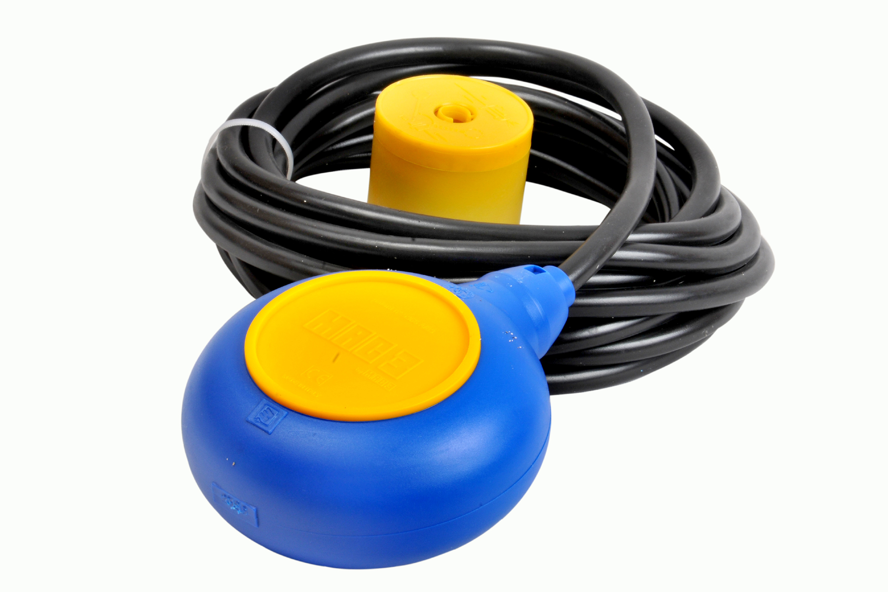 | Level Switch Cable Float Switch is mainly used for the automatic working of small pumps and cellar emptying pumps in liquids a little bit agitated. View product → |
When one switch is not enough for overfill protection
Add an independent high-high level switch when an overflow could injure people, release hazardous liquid, damage equipment, breach containment, or stop production. It belongs alongside the normal level transmitter and control loop, not downstream of them.
The extra device provides independent overflow protection only when it has a genuinely separate path from detection to corrective action. A second alarm on the same transmitter is redundancy in indication, not a separate protective layer.
A shared component can defeat both the normal control and the supposed backup:
- One impulse line or process connection can block, leak, or freeze before either function detects the true level.
- One power supply can remove both signals during a fuse, wiring, or distribution failure.
- One PLC, I/O card, or communication network can lose both the measurement and the trip command.
- One software routine can contain the same scaling, logic, or configuration error in both functions.
Place the high-high switch at the actual maximum permitted liquid elevation, with freeboard for inflow and shutdown delay. A convenient nozzle can sit above or below that elevation because nozzle length, vessel tilt, dead volume, or an obstruction changes where the switch actually responds.
A SIL level switch does not make the complete function SIL-rated. IEC 61511 assessment also covers the sensor, logic solver, final element, proof-test interval, diagnostics, common-cause failures, and response time. Record the as-installed trip elevation, alarm action, reset behaviour, and bypass status; a bypassed switch is degraded protection, not protection you can count on.
How to commission and proof-test the complete overflow shutdown
Level switch commissioning proves that the installed device and the complete overflow shutdown act together. Confirm the trip elevation leaves freeboard for inflow, switch response, logic processing, and pump or valve stopping time; a point switch does not measure remaining tank volume.
1. Record the as-installed trip elevation against a tank datum, then raise liquid to the switch or use a calibrated simulation that reaches the actual trip point. Record the normal and alarm contact states.
2. Run the overflow shutdown test through the logic solver and final element. Confirm the alarm annunciates, the filling pump stops or inlet valve closes, and the commanded position occurs. Continuity at switch terminals alone can miss a seized float, failed relay, incorrect PLC logic, or stuck valve.
3. Remove instrument power and open the input circuit to verify the designed fault response. In a de-energize-to-trip circuit, both conditions should produce the safe-state command; contact labeling alone does not prove this.
4. Restore the initiating condition and power, then verify whether the system remains tripped until a deliberate reset. Test the reset location, required operator action, alarm clearing, and restart interlock so a power return cannot restart filling unexpectedly.
5. Check every bypass or inhibit. A bypassed high-high switch is a degraded protection layer, so require named authorization, a start and expiry time, compensating operating measures, and a recorded return to service.
A switch’s SIL marking does not rate the whole function; sensor, logic solver, final element, diagnostics, proof-test interval, independence, and response time must be assessed together.
Frequently asked questions
How does a level switch turn a rising liquid level into corrective action?
The sensing element changes an electrical contact at a preset elevation. A relay, contactor, PLC, or pump controller then stops filling or closes the inlet valve.
How should you wire a level switch for a safe shutdown response?
Connect the switch to the shutdown circuit so the pump stops or the inlet valve closes when the high-level condition occurs. Choose the contact state and relay logic to create a safe response during power or signal loss.
How do liquid properties and mounting location affect overflow-switch reliability?
Select the switch for the liquid's density, viscosity, temperature, chemical compatibility, and solids content. Mount it where turbulence, foam, inlet flow, and the actual overflow elevation will not cause false trips or delayed action.
When is one level switch not enough for overflow protection?
Add independent high-high protection when an equipment failure, blocked outlet, hazardous liquid, large tank volume, or required shutdown integrity exceeds one switch's capability.
How do you commission and proof-test a complete overflow shutdown?
Raise the level or use a controlled simulation to verify the switch changes state, the relay or PLC receives it, the pump stops, the valve moves to its safe position, and alarms identify the event. Record the trip point and test result.
Related products
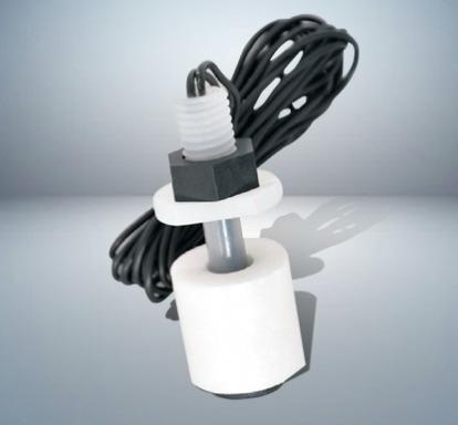 | Level Switch Plastic Miniature Level Switch is available in PP construction with PP Float Switching Voltage: 24V DC Switching current: 0.1A Mounting thread size:... View product → |
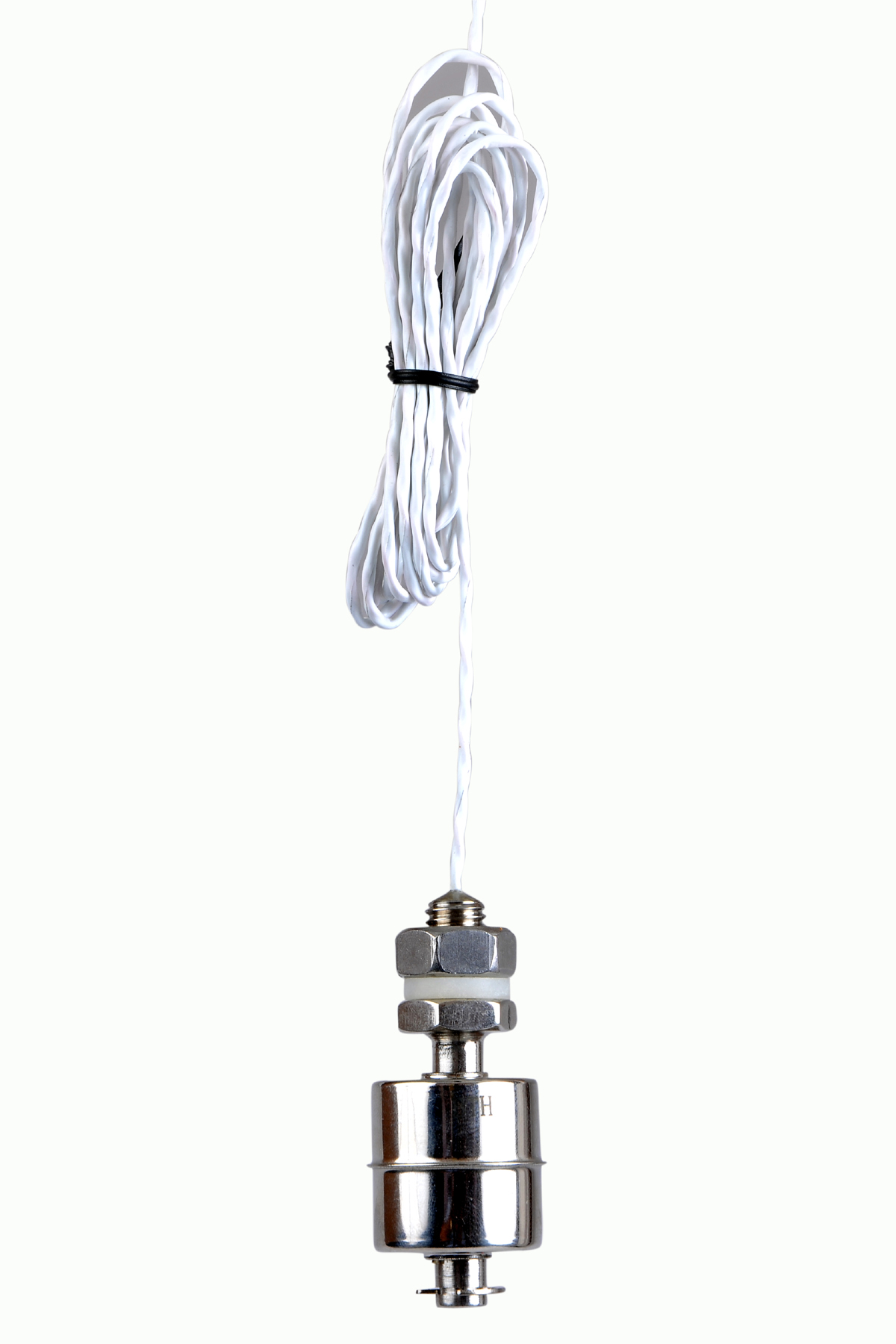 | Level Switch Stainless steel level switch - Miniature Stainless steel Miniature Level Switch is a compact construction, suitable for mounting vertically. View product → |
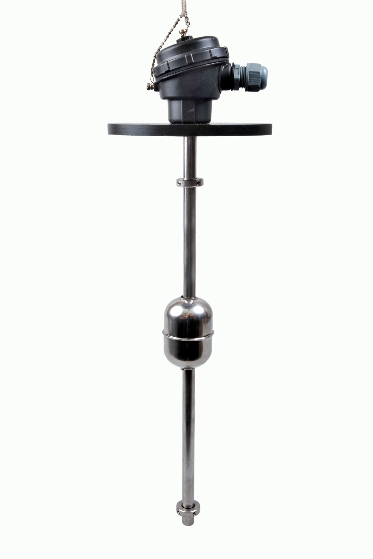 | Level Switch The Magnetic Level Switch consists of the non-abrasive float carrying permanent magnet and non-ferrous stem carrying one. View product → |
 | Level Sensor Atex approved Float Level Transmitter : Over All Length: 300mm to 5000mm Input: 16V DC to 30V DC Output: 4-20mA / 0-10V DC Resolution: 5mm / 10mm... View product → |